
Technical Product Specification

Hard Disk Drive Support Intel® Server System SR1695WB TPS
Revision 1.4
Intel order number: E92079-005
32
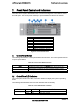
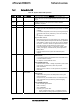
3) SATA/SAS Drive Control Connectors (J1A2, J4A1, J6A2, and J8A2)
The passive backplane includes four drive control connectors. These are used to attach
SATA/SAS cables from the backplane to either the SATA ports on the server board, or to
SAS/SATA ports from an add-in card. Each drive control connector has the following pin-out.
Table 35. SATA/SAS Drive Control Connector Pin-out
Pin# Description
1 GROUND
2 SATA # TX_DP (# = 0,1,2)
3 SATA # TX_DN (# = 0,1,2)
4 GROUND
5 SATA # RX_DN (# = 0,1,2)
6 SATA # RX_DP (# = 0,1,2)
7 GROUND
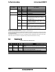
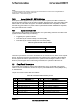
4) System Management(IPMB) Connector(J9A1)
The backplanes provide connectors to interface with system management buses. The
following tables define the pin-out for each of these connectors.
Table 36. IPMB Connector Pin-out
Pin # Description
1 SMB_5VSB_IPMB_DAT
2 GND
3 SMB_5VSB_IPMB_CLK
4 SMB_PWR_IPMB_CONN
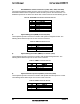
5) System Management Bus (SMBus) Connector (J8A1)
The backplanes provide connectors to interface with System Management Bus. The
following tables define the pin-out for each of this connector.
Table 37. SMBus Connector Pin-out
Pin # Description
1 SMB_5V_DAT
2 GND
3 SMB_5V_CLK
4 GND
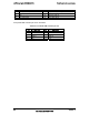
6) System General Purpose IO (SGPIO) Connector (J4A2)
The backplanes provide connectors to interface with System General Purpose IO control.
The following tables define the pin-out for each of this connector.
Table 38. SGPIO Connector Pin-out
Pin # Description
1 Data In
2 Data Out
3 End Control
4 Clock