
Technical Product Specification


Intel® Server System SR1695WB TPS Hard Disk Drive Support
Revision 1.4 31
Intel order number: E92079-005
6.3.5 Backplane Connector Definition
The backplanes include several different connectors. This section defines the purpose and
pin out associated with each.
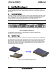
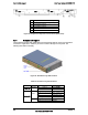
1) Power Connector(J1A1, J5A1)
The backplane provides power to the three hard drive bays and the slim-line drive bay. An 8-
pin power cable is routed from the power supply and plugs into two 4-pin shrouded plastic
PC power connector on the backplane. The following table shows the power connector pin-
out.
Table 33. Backplane Power Connector Pin-out
Pin Signal Pin Signal
1 COM 3 +5VDC
2 +12VDC 4 +3V3DC
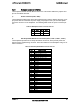
2) Hot-Swap SATA/SAS Drive Connectors(JC2L1, JC4L1, JC6L1, JC9L1)
The backplanes provide four hot-swap SATA/SAS connectors, which provide power and
signals using a single docking connector. Each drive attaches to the backplane using one of
these connectors.
Table 34. Hot-Swap SATA/SAS Connector Pin-out
Pin# Signal Description
SI Ground
S2 SAS#_TX_DP (# = 0…2)
S3 SAS#_TX_DN (# = 0…2)
S4 Ground
S5 SAS#_RX_DN (# = 0…2)
S6 SAS#_RX_DP (# = 0…2)
S7 Ground
S8 Not Used
S9 Not Used
S10 Not Used
S11 Not Used
S12 Not Used
S13 Not Used
S14 Not Used
P1 Not Used
P2 Not Used
P3 Not Used
P4 Ground
P5 Ground
P6 P3V3
P7 P5V
P8 P5V
P9 P5V
P10 Ground
P11 LED_SAS#_ACT_L (# = 0…2)
P12 Ground
P13 P12V
P14 P12V
P15 P12V
PTH0 Ground
PTY1 Ground