
Technical Product Specification

Power Sub-System Intel® Server System SR1695WB TPS
Revision 1.4
Intel order number: E92079-005
16
3.4 Control And Indicator Functions
Signals that can be defined as low true or high true shall adopt the following conversion:
signal# = low true.
3.4.1 PSON#(Power supply enable)
Both AC and DC power supply module’s PSON# signal is required to remotely turn on/off the
+12V output in the power supply. When the power supply is in standby mode the power
supply fan shall be OFF. PSON# is pulled to a standby voltage by a pull-up resistor internal
to the power supply. See Table 15.
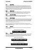
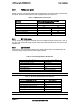
Table 15. PS ON# Signal Characteristics.
Signal Type Pull-up To Housekeeping Voltage In Power Supply
PSON# =Low, PSKILL=Low ON
PSON# =Open, PSKILL=Low or Open OFF
PSON# =Low, PSKILL=Open OFF
Min Max
Logic level low(power supply ON) 0V 1.0V
Logic level high(power supply OFF) 2.0V 5.25V
Source current, Vpson=low N/A 1mA
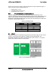
3.4.2 PSKILL/A1
The purpose of the PSKILL/A1 pin is to allow for hot swapping of the power supply. The
PSKILL/A1 pin on the power supply is shorter than the other signal pins. The mating pin of
this signal in the system shall be tied to ground. Internal to the power supply, the PSKILL/A1
pin shall be connected to a standby voltage through a pull-up resistor. Upon receiving a
<4.1V state at the PSKILL/A1 pin, a PSON# signal shall enable the power supply to turn on.
See Table 16.
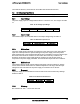
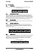
Table 16. PSKILL# Signal Characteristics
Signal Type(Input Signal To Supply) Accepts A Ground Input From The System. Pull-up To VSB Located In
The Power Supply
PSON# =Low, PSKILL/A1=Low ON
PSON# =Open, PSKILL/A1=Low or Open OFF
PSON# =Low, PSKILL/A1=Open OFF
Min Max
Logic level low(power supply ON) 0V 4.1V(for AC Module)/1.0V(For
DC Module)
Logic level high(power supply OFF) 4.1V(For AC Module)/2.0V(For
DC Module)
5.25V
Source current, Vpskill/A1=low N/A 4mA