
Technical Product Specification
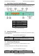

Intel® Server System SR1690WB TPS Front Panel Control and Indicators
Revision 1.7 35
Intel order number: E72797-009
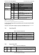
7.2.3 System Identification LED
The system ID LED provides a visual indication of a system being serviced. The state of the
system ID LED is affected by the following:
Toggled by the system ID button
Controlled by the Chassis Identify command (IPMI)
Controlled by the Chassis Identify LED command (OEM)
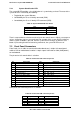
Table 38. System ID LED Indicator States
State
LED State
Identify active via button Solid on
Identify active via command ~1 Hz blink
Off Off
There is no precedence or lock-out mechanism for the control sources. When a new request
arrives, all previous requests are terminated. For example, if the system ID LED is blinking
and the system ID button is pressed, then the system ID LED changes to solid on. If the
button is pressed again with no intervening commands, the system ID LED turns off.
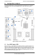
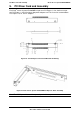
7.3 Front Panel Connectors
Front Panel uses 2 cables to connect with motherboard, one is 24-pin SSI control panel
cable to J1D3 on motherboard, another is 10-pin 2 ports USB cable to J9A2 (USB port 0/1)
on motherboard.
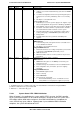
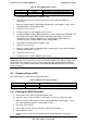
The pin-out for SSI control cable is as below:
Table 39. Front Panel SSI connector pin-out
Pin
Signal Name
Pin
Signal Name
1
P3V3_STBY (Power LED Anode)
2
P3V3_STBY (Front Panel Power)
3
Key
4
P5V_STBY (ID LED Anode)
5
FP_PWR_LED_N
6
FP_ID_LED_BUF_N
7 P3V3 (HDD Activity LED Anode) 8 FP_LED_STATUS_GREEN_N
9 LED_HDD_ACTIVITY_N 10 FP_LED_STATUS_A MBER_N
11 FP_PWR_BTN_N 12 NIC1_ACT_LED_N
13
GND (Power Button GND)
14
NIC1_LINK_LED_N
15
BMC_RST_BTN_N
16
SMB_SENSOR_3V3STB_DATA
17
GND (Reset GND)
18
SMB_SENSOR_3V3STB_CLK
19
FP_ID_BTN_N
20
FP_CHASSIS_INTRU
21
NC
22
NIC2_ACT_LED_N
23
FP_NMI_BTN_N
24
NIC2_LINK_LED_N
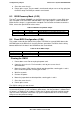
Front panel USB connector pin-out is as follows:
Table 40. Front Panel USB connector pin-out
Pin
Signal Name
Pin
Signal Name
1
NC
2
Key Pin
3
GND
4
GND
5
USB_P
6
USB_P
7
USB_N
8
USB_N
9
+5V
10
+5V