
Technical Product Specification

Front Panel Control and Indicators Intel® Server System SR1690WB TPS
Revision 1.7
Intel order number: E72797-009
34
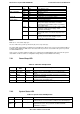
Color
State
Criticality
Description
Green Solid on Ok System ready
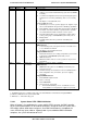
Green Blink Degraded BIOS detected
1. Unable to use all of the installed memory (more than one DIMM
installed).
1
2. In a mirrored configuration, when memory mirroring takes place
and system loses memory redundancy. This is not covered by
(2).
1
3. PCI Express* correctable link errors.
Integrated BMC detected
1. Redundancy loss such as a power supply or fan. Applies only if
the associated platform subsystem has redundancy capabilities.
2. CPU disabled – if there are two CPUs and one CPU is disabled.
3. Fan alarm – Fan failure. Number of operational fans should be
more than minimum number needed to cool the system.
4. Non-critical threshold crossed – Temperature, voltage, power
nozzle, power gauge, and PROCHOT2 (Therm Ctrl) sensors.
5. Battery failure.
6. Predictive failure when the system has redundant power
supplies.
Amber Blink Non-critical Non-fatal alarm – system is likely to fail
BIOS Detected
1. In non-mirroring mode, if the threshold of ten correctable errors
is crossed within the window.
1
2. PCI Express* uncorrectable link errors.
Integrated BMC Detected
1. Critical threshold crossed – Voltage, temperature, power nozzle,
power gauge, and PROCHOT (Therm Ctrl) sensors.
2. VRD Hot asserted.
3. Minimum number of fans to cool the system are not present or
have failed.
Amber Solid on Critical, non-
recoverable
Fatal alarm – system has failed or shutdown
BIOS Detected
1. DIMM failure when there is one DIMM present and no good
memory is present.
1
2. Run-time memory uncorrectable error in non-redundant mode.
1
3. CPU configuration error (for instance, processor stepping
mismatch).
Integrated BMC Detected
1. CPU CATERR signal asserted.
2. CPU 1 is missing.
3. CPU THERMTRIP.
4. No power good – power fault.
• Power Unit Redundancy sensor – Insufficient resources
offset (indicates not enough power supplies are present).
Notes:
1. The BIOS detects these conditions and sends a Set Fault Indication command to the Integrated BMC to
provide the contribution to the system status LED
2. Blink rate is ~ 1Hz at 50% duty cycle.
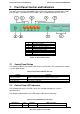
7.2.2.1 System Status LED – BMC Initialization
When AC power is first applied to the system and 5V-STBY is present, the BMC controller
on the server board requires 15-20 seconds to initialize. During this time, the system status
LED will be solid on, both amber and green. Once BMC initialization has completed, the
status LED will stay green solid on. If power button is pressed before BMC initialization
completes, the system will not boot to POST.