
Technical Product Specification


Hard Disk Drive Support Intel® Server System SR1690WB TPS
Revision 1.7
Intel order number: E72797-009
30
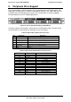
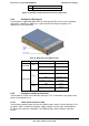
Table 27. Backplane Power Connector Pin-out
Pin
Signal
Pin
Signal
1 COM 3 +5VDC
2
+12VDC
4
+3V3DC
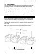
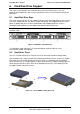
6.3.5.2 Hot-Swap SATA/SAS Drive Connectors(JC2L1, JC4L1, JC6L1, JC9L1)
The backplanes provide four hot-swap SATA/SAS connectors, which provide power and
signals using a single docking connector. Each drive attaches to the backplane using one of
these connectors.
Table 28. Hot-Swap SATA/SAS Connector Pin-out
Pin#
Signal Description
SI
Ground
S2
SAS#_TX_DP (# = 0…2)
S3
SAS#_TX_DN (# = 0…2)
S4
Ground
S5
SAS#_RX_DN (# = 0…2)
S6
SAS#_RX_DP (# = 0…2)
S7
Ground
S8
Not Used
S9
Not Used
S10
Not Used
S11
Not Used
S12
Not Used
S13
Not Used
S14
Not Used
P1
Not Used
P2
Not Used
P3
Not Used
P4
Ground
P5
Ground
P6
P3V3
P7
P5V
P8
P5V
P9
P5V
P10
Ground
P11
LED_SAS#_ACT_L (# = 0…2)
P12
Ground
P13
P12V
P14
P12V
P15
P12V
PTH0
Ground
PTY1
Ground
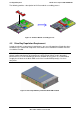
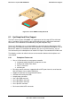
6.3.5.3 SATA/SAS Drive Control Connectors (J1A2, J4A1, J6A2, and J8A2)
The passive backplane includes four drive control connectors. These are used to attach
SATA/SAS cables from the backplane to either the SATA ports on the server board, or to
SAS/SATA ports from an add-in card. Each drive control connector has the following pin-out.
Table 29. SATA/SAS Drive Control Connector Pin-out
Pin#
Description
1
GROUND
2
SATA # TX_DP (# = 0,1,2)
3
SATA # TX_DN (# = 0,1,2)
4
GROUND
5
SATA # RX_DN (# = 0,1,2)
6
SATA # RX_DP (# = 0,1,2)
7
GROUND