
Technical Product Specification


Intel® Server System SR1690WB TPS Hard Disk Drive Support
Revision 1.7 29
Intel order number: E72797-009
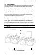
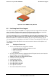
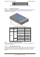
A 4-pin power connectors 1~2 for backplane
F 4-pin IPMB connector
Figure 23. Backplane Component and Connectors (Back View)
6.3.4 Backplane LED Support
The backplanes support both HDD online and activity/fault LEDs for each of the hard drive
connectors. A light duct in HDD tray is used to conduct LED light to front panel. The
following lists LED functionality.
Table 26. Hard Drive Tray LED Functions
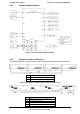
6.3.5 Backplane Connector Definition
The backplanes include several different connectors. This section defines the purpose and
pinout associated with each.
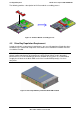
6.3.5.1 Power Connector(J1A1, J5A1)
The backplane provides power to the three hard drive bays and the slim-line drive bay. An 8-
pin power cable is routed from the power supply and plugs into two 4-pin shrouded plastic
PC power connector on the backplane. The following table shows the power connector
pin-out.
LED color Condition Description
Power LED
Blue
ON HDD On-line
OFF HDD Not On-line
Activity LED
Green
OFF
Standby/Stopped
Flashing(on 0.5s off 0.5s)
Spin-Up/Spin-Down
ON
Active/Idle power
Flashing(on 1s off 1s)
Formatting
Amber
ON Fault
Flashing(on 0.5s off 0.5s) Rebuild