
Technical Product Specification


Hard Disk Drive Support Intel® Server System SR1690WB TPS
Revision 1.7
Intel order number: E72797-009
28
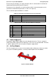
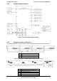
6.3.2 Backplane Block Diagram:
Figure 21. Passive Backplane Block Diagram
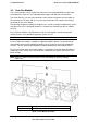
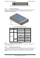
6.3.3 Backplane Connector Definition
The following diagrams show the layout of major components and connectors for backplane.
A HDD Connectors 0~3 (left to right)
B HDD On-line LEDs 0~3 (left to right)
C HDD Act/Fault LEDs 0~3 (left to right)
Figure 22. Backplane Component and Connectors (Front View)
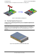
A
4-pin power connectors 1~2 for backplane
B
SATA/SAS connectors 0~3 (right to left)
C
4-pin SGPIO connector
D 4-pin SMBus connector
E 3-pin SES connector