
Technical Product Specification


Intel® Server System SR1690WB TPS Cooling Sub-System
Revision 1.7 23
Intel order number: E72797-009
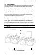
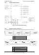
Each memory fan (Group A) uses 8-pin connector, which is connected to fan connector on
mother board (Connector BB and Q in Figure 5).
Each processor fan (Group B) uses 4-pin connector, which is connected to processor fan
connector on mother board (Connector S, T and Y, Z in Figure 5).
The fan connector pin-out definition is as follows:
Table 22. 4-pin Connector Pin-Out for Processor Cooling Fan
Pin
Signal Name
Description
1 GND Ground
2 12V Power Supply +12 V
3 Tach Out FAN_TACH signal output
4
PWM In
PWM signal input
Table 23. 8-pin Connector Pin-Out for Memory Cooling Fan
Pin
Signal Name
Description
1
GND
Ground
2
12V
Power Supply 12 V
3 Tack0 Tach signal output from FAN0
4 PMW0 PWM control signal input for FAN0
5 GND Ground
6 12V Power Supply 12 V
7
Tach1
Tach signal output from FAN1
8
PWM1
PWM control signal input for FAN1
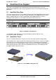
4.3 Power Supply Fan
Each power supply module supports one non-redundant 40 mm fan. The fans control the
cooling of the power supply and some drive bays. These fans are not replaceable. Therefore,
if a power supply fan fails, you must replace the power supply module.
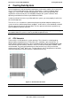
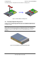
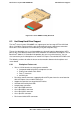
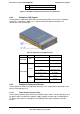
4.4 Air Duct Module
The chassis requires the use of an air duct module to direct airflow over critical areas within
the system. The following provides a summary and description of Air Duct Module.
Figure 14. Air Duct Module