
Technical Product Specification


Cooling Sub-System Intel® Server System SR1690WB TPS
Revision 1.7
Intel order number: E72797-009
22
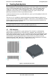
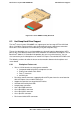
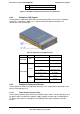
4.2 Four-Fan Module
The system includes a fan assembly consisting of four managed 40x40x56 mm dual-rotor,
multi-speed fans. Four fans are separated into two types with different fan connectors.
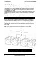
The center two fans use two 4-pin connectors; each matches the processor fan header on
the server board. The outer two fans use one 8-pin connector; each matches the memory
fan header on the server board.
They provide the primary cooling for the processors, memory, and the hard drive bays on the
front panel. Each fan is designed for tool-less insertion to or removal from the fan module
housing.
The system fan module is designed for ease of use and supports several management
features that the server board management system can use.
Note: The fans are NOT hot-swappable. You must turn off the system to replace a failed fan.
Each fan within the module is capable of supporting multiple speeds. Fan speed changes
automatically when internal ambient temperature of the system or processor temperature
changes. The fan speed control algorithm is programmed into the server board’s BIOS.
Each fan connector within the module supplies a tachometer signal that allows the BMC to
monitor the status of each fan. If one of the fans should fail, the system fault LED on front
panel will light.
Note: There is a spare fan kit that contains one CPU cooling fan and one memory
cooling fan.
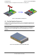
A
Memory Cooling Fans
B
Processor Cooling Fans
Figure 13. Fan Module Assembly