
Technical Product Specification

2BPower Sub-System Intel® Server System SR1690WB TPS
Revision 1.7
Intel order number: E72797-009
12
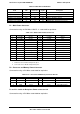
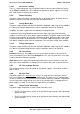
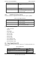
Table 6. P3 and P4 – Backplane Power Connector Pin-out
Pin
Signal
18AWG Color
1
GND
Black
2
+12V2
Yellow/Black Strip
3
+5VDC
Red
4
+3.3VDC
Red
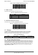
P5 – PMBus Connector
Connector housing: 5-pin Molex 50-57-9705 or equivalent
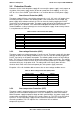
Table 7. P5 – PMBus/Power Signal Connector Pin-out
Pin
Signal
24 AWG Color
1
I2C Clock
White/Yellow Stripe
2
I2C Data
White/Yellow Stripe
3
I2C Alert
White
4
Return
Black
5
N.C.
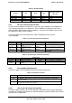
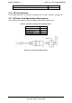
P6 – CD/DVD Drive SATA Power connector
Connector housing: 4-Pin Molex 43640-0400 or equivalent
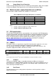
Table 8. P6 – CD/DVD Drive SATA Power Connector Pin-out
Pin Signal 18AWG Color
1
+5VDC
Red
2
+5VDC
Red
3
GND
Black
4
GND
Black
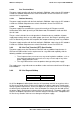
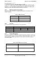
3.3 Efficiency
The following table provides the required minimum efficiency level at various loading
conditions. These are provided at three different load levels; 100%, 50%, and 20%.
Efficiency was tested over an AC input voltage range of 115 VAC to 220 VAC.
Table 9. Power Supply Efficiency
Loading
100% of maximum
50% of maximum
20% of maximum
Minimum Efficiency
>85%
>88%
>85%
3.4 AC Input Voltage Specification
The power supply operates within all specified limits over input voltage range shown in the
following table. Harmonic distortion of up to 10% THD will not cause the power supply to go
out of specified limits. The power supply shall power off if the AC input is less than 75VAC
+/-5VAC range. The power supply shall start up if the AC input is greater than 85 VAC +/-4
VAC. Application of an input voltage below 85 VAC will not cause damage to the power
supply, including a fuse blow.