
Technical Product Specification

Intel® Server System SR1690WB TPS 2BPower Sub-System
Revision 1.7 11
Intel order number: E72797-009
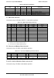
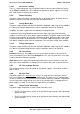
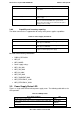
Table 3. Cable Harness Definition
From
Length
mm
To
connector #
Number
of pins
Description
Backplane cover exit hole 350 P1 2x12 Main power connector
Backplane cover exit hole 630 P2 2x4 Processor and memory power connector
Backplane cover exit hole 480 P3 2x2 Cable for Backplane power1
Backplane cover exit hole
270
P4
2x2
Cable for Backplane power2
Backplane cover exit hole
300
P5
1x5
Cable for PMBUS
Backplane cover exit hole
25
P6
1x4
CD/DVD drive SATA Power Connector
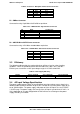
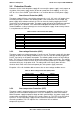
P1 – Main Power Connector
Connector housing: 24-Pin Molex* Mini-Fit Jr.
39-01-2245 or equivalent.
Table 4. P1 – Main Power Connector Pin-out
Pin
Signal
18 AWG Color
Pin
Signal
18 AWG Color
1
+3.3 VDC
Orange
13
+3.3 VDC
Orange
2
+3.3 VDC
Orange
14
-12 VDC
Blue
3
GND
Black
15
GND
Black
4
+5 VDC*
Red
16
PSON#
Green
5
GND
Black
17
GND
Black
6 +5 VDC Red 18 GND Black
7 GND Black 19 GND Black
8
PWR OK
Gray
20
Reserved
N.C.
9 5VSB Purple 21 +5 VDC Red
10
+12V3
Yellow/Blue Stripe
22
+5 VDC
Red
11
+12V3
Yellow/Blue Stripe
23
+5 VDC
Red
12
+3.3 VDC
Orange
24
GND
Black
Notes:
1. 5V Remote Sense Double Crimped into pin 4.
2. 3.3V Locate Sense Double Crimped into pin 2.
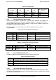
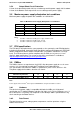
P2 – Processor and Memory Power Connector
Connector housing: 8-Pin Molex 39-01-2085 or equivalent
Table 5. P2 – Processor and Memory Connector Pin-out
Pin
Signal
18 AWG Color
Pin
Signal
18 AWG Color
1 GND Black 5 +12V1 Yellow
2 GND Black 6 +12V1 Yellow
3 GND Black 7 +12V1 Yellow/Black Stripe
4 GND Black 8 +12V1 Yellow/Black Stripe
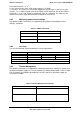
P3 and P4 – Cable for Backplane Power connector 1&2
Connector housing: 4-Pin Molex 39-01-2040 or equivalent