Intel® Server System SR1690WB Technical Product Specification Intel order number: E72797-009 Revision 1.
Revision History Intel® Server System SR1690WB TPS Revision History Date ii July 4, 2009 Revision Number 1.0 Modifications August 8, 2009 1.1 Changes on PSU cables and onboard SATA port numbering. September 22, 2009 March 15, 2010 March 18, 2010 November 10, 2010 December 30, 2010 March 20, 2010 1.2 1.3 1.4 1.5 1.6 1.7 HDD LED status updated and added optional chassis rail kit. Updated the supported processor list. Removed CCC certificates. Updated iBMC memory size. Updated LAN IOAT2 support.
Intel® Server System SR1690WB TPS Disclaimers Disclaimers Information in this document is provided in connection with Intel® products. No license, express or implied, by estoppel or otherwise, to any intellectual property rights is granted by this document.
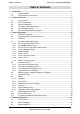
Table of Contents Intel® Server System SR1690WB TPS Table of Contents 1. Introduction ........................................................................................................................1 1.1 Chapter Outline ......................................................................................................1 1.2 Server Board Use Disclaimer .................................................................................1 2. Product Overview ...........................................
Intel® Server System SR1690WB TPS Table of Contents 4.4 Air Duct Module ....................................................................................................23 4.5 Drive Bay Population Requirement.......................................................................24 5. Peripheral Drive Support .................................................................................................25 6. Hard Disk Drive Support ......................................................................
Table of Contents Intel® Server System SR1690WB TPS Appendix A: Integration and Usage Tips ..............................................................................51 Appendix B: POST Code LED Decoder .................................................................................52 Appendix C: Video POST Code Errors ..................................................................................57 Appendix D: Jumper Block Settings and Usage ........................................................
Intel® Server System SR1690WB TPS List of Figures List of Figures Figure 1. System Overview (HDD and Memory DIMMs are not included in package) ................. 4 Figure 2. Major Chassis Components .........................................................................................5 Figure 3. Drive Bay Overview......................................................................................................6 Figure 4. Intel® Server Board S5500WB SSI-compliant .....................................
List of Tables Intel® Server System SR1690WB TPS List of Tables Table 1. System Feature Set.......................................................................................................3 Table 2. Chassis Dimensions ......................................................................................................5 Table 3. Cable Harness Definition .............................................................................................11 Table 4. P1 – Main Power Connector Pin-out .........
Intel® Server System SR1690WB TPS List of Tables Table 47. System Office Environmental Summary ....................................................................41 Table 48. Serviceability and Availability ....................................................................................41 Table 49. Product Safety and Electromagnetic (EMC) Compliance ........................................... 43 Table 50. Product Ecology Compliance......................................................................
List of Tables Intel® Server System SR1690WB TPS < This page is intentionally left blank. > x Intel order number: E72797-009 Revision 1.
Intel® Server System SR1690WB TPS 1. 0BIntroduction Introduction This Technical Product Specification (TPS) provides system specific information detailing the features, functionality, and high-level architecture of the Intel® Server System SR1690WB. You should also reference the Intel® Server Board S5500WB Technical Product Specification to obtain greater detail of functionality and architecture of the server board integrated in this server system.
0BIntroduction Intel® Server System SR1690WB TPS components fail or the server board does not operate correctly when used outside any of their published operating or non-operating limits. 2 Intel order number: E72797-009 Revision 1.
Intel® Server System SR1690WB TPS 2. 1BProduct Overview Product Overview The Intel® Server System SR1690WB is a rack mount 1U server system, purpose-built for high-energy efficiency and lowest total cost of ownership in dense computing applications. The system is integrated with an Intel® Server Board S5500WB and supports up to four hotswap SAS or SATA hard drives. This chapter provides a high-level overview of the system features.
1BProduct Overview Intel® Server System SR1690WB TPS Feature Description Two sets of DIMM fans Add-in Adapter Support ® Intel Server Board S5500WB SSI-compliant One riser slot supporting full-height or low-profile 1U and 1U MD2 PCI Express* x16 riser cards. ® Two connectors supporting double- and single-wide Intel I/O Expansion Modules.
Intel® Server System SR1690WB TPS 2.2 1BProduct Overview System Dimensions Table 2. Chassis Dimensions 2.3 Height 43 mm 1.69 inches Width without rails 451.17 mm 17.76 inches Width with rails 482 mm 18.97 inches Depth without CMA Weight Chassis – basic configured (0 drives) Chassis – fully configured (4 drives) 671.08 mm 26.42 inches 11.15 kg 13.32 kg 24.58 lbs 29.
1BProduct Overview Intel® Server System SR1690WB TPS Device Slim-line USB Floppy Drive Intel® Server System SR1690WB No Support SATA Drives (3.5-inch or 2.5-inch) Up to four SAS Drives (3.5-inch or 2.5-inch) Up to four A System Control Panel B Slim-line drive bay C HDD Power LED D HDD Activity/Fault LED E Hard drive bays 0~3 Figure 3. Drive Bay Overview 2.
Intel® Server System SR1690WB TPS 1BProduct Overview ® Figure 5.
1BProduct Overview Intel® Server System SR1690WB TPS Figure 6. Connector and Component Definitions A AC Power Receptacle F Video connector B NIC 1 connector G Management Network Interface (optional) C USB port 2, 5, 8, 9 H IO module external connector 1 (optional) D NIC 2 connector I IO module external connector 2 (optional) E RJ-45 serial B port J Add-in card bracket (full height) Figure 7.
Intel® Server System SR1690WB TPS 1BProduct Overview Figure 8. Light-Guided Diagnostic LED Locations 2.6 Rack and Cabinet Mounting Options The chassis was designed to support 19 inches wide by up to 30 inches deep server cabinets. The system supports the following Intel rack mount options: A fixed mount relay rack/cabinet mount kit which you can configure to mount the system into either a 2-post rack or 4-post cabinet.
2BPower Sub-System 3. Intel® Server System SR1690WB TPS Power Sub-System The system includes a 650-W power supply unit, which is 80 plus energy efficiency, demonstrating climate saver with silver rating. 3.1 Mechanism overview The power supply will have a simple retention mechanism to retain the power supply once it is inserted. This mechanism shall withstand the specified mechanical shock and vibration requirements. The power supply module will be fixed on the chassis with screws. Figure 9.
Intel® Server System SR1690WB TPS 2BPower Sub-System Table 3.
2BPower Sub-System Intel® Server System SR1690WB TPS Table 6. P3 and P4 – Backplane Power Connector Pin-out Pin 1 2 3 4 Signal GND +12V2 +5VDC +3.3VDC 18AWG Color Black Yellow/Black Strip Red Red P5 – PMBus Connector Connector housing: 5-pin Molex 50-57-9705 or equivalent Table 7. P5 – PMBus/Power Signal Connector Pin-out Pin 1 2 3 4 5 Signal I2C Clock I2C Data I2C Alert Return N.C.
Intel® Server System SR1690WB TPS 2BPower Sub-System Table 10. AC Input Rating Parameter Voltage (100) Voltage (120) Voltage (240) Frequency 3.4.1 Min. 90 Vrms 108 Vrms 180 Vrms 47 Hz Rated Max. 100 Vrms 120 Vrms 200-240 Vrms 110 Vrms 132 Vrms 264 Vrms 63 Hz Max. input current at Min. Vrms 6.7 Arms 5.6 Arms 3.4 Arms AC Line Transient Specification AC line transient conditions are defined as “sag” and “surge” conditions. Sag conditions are also commonly referred to as a “brown-out”.
2BPower Sub-System 3.4.2.2 Intel® Server System SR1690WB TPS Fast Transient/Burst The power supply complies with the limits defined in EN55024: 1998 using the IEC 61000-44:1995 test standard and performance criteria B defined in Annex B of CISPR 24. Test to meet the level 3 requirement. 3.4.2.3 Radiated Immunity The power supply complies with the limits defined in EN55024: 1998 using the IEC 61000-43:1995 test standard and performance criteria A defined in Annex B of CISPR 24. 3.4.2.
Intel® Server System SR1690WB TPS 3.4.4.1 2BPower Sub-System AC Line 5VS B Holdup The 5 VSB output voltage will stay in regulation under its full load (static or dynamic) during an AC dropout of 70 ms min (=5VSB holdup time) whether the power supply is in an ON or OFF state (PSON asserted or de-asserted). 3.4.5 Power Recovery The power supply will recover automatically after an AC power failure. AC power failure is defined as any loss of AC power that exceeds the dropout criteria. 3.4.5.
2BPower Sub-System 3.5 Intel® Server System SR1690WB TPS Protection Circuits Protection circuits inside the power supply will cause only the power supply’s main outputs to shut down. If the power supply latches off due to a protection circuit tripping, an AC cycle OFF for 15 sec and a PSON# cycle HIGH for 1 sec shall be able to reset the power supply. 3.5.1 Over-Current Protection (OCP) The power supply will have current limits to prevent the +3.
Intel® Server System SR1690WB TPS 3.5.4 2BPower Sub-System Output Short Circuit Protection A short circuit placed to ground shall cause no damage and the power supply shall shutdown. A short circuit between each output shall cause no damage to the power supply. 3.6 Maximum power supply dissipation test conditions Maximum power supply dissipation test conditions at 115/230 VAC. Table 16. Maximum Power Supply Dissipation Test Conditions 115 VAC 230 VAC Notes: 1. 2. 3. 3.
2BPower Sub-System Intel® Server System SR1690WB TPS Literal data format: X = Y · 2N X = the sensor value in volts, amps, watts, degrees C, or RPM Y = mantissa. The mantissa is the variable components that changes as the sensor value changes. Y is a 16-bit unsigned value for the READ_VOUT command. For all other READ commands, Y is an 11-bit signed 2’s compliment value. N = exponent. The exponents are fixed for each power supply and define the resolution for each sensor. 3.8.
Intel® Server System SR1690WB TPS 2BPower Sub-System Command Description READ_TEMPERATURE_1, _2, _3 Returns the temperature in degrees C of temp sensors 1, 2, and 3. FAN_CONFIG_1_2 Returns the configuration of Fan 1 and Fan 2 in the power supply. FAN_COMMAND_1,_2 Allows the system to request fans in the power supply to be set to the defined RPM. The system cannot cause the power supply to run slower than the power supply needs for cooling. 3.8.
2BPower Sub-System Intel® Server System SR1690WB TPS Power Supply Condition LED Output ON and OK Solid GREEN 3.10 AC Inlet Connector The AC input connector is an IEC 320 C-14 power inlet. This inlet is rated for 15 A/250 VAC. 3.11 AC Power Cord Specification Requirements The AC power cord used must meet the following specification requirements: Table 21.
Intel® Server System SR1690WB TPS 4. Cooling Sub-System Cooling Sub-System Several components and configuration requirements make up the cooling sub-system of the chassis. These include processors, chipsets, VR heatsinks, system fan module, power supply fans, CPU air duct, and drive bay population. All are necessary to provide and regulate the air flow and air pressure needed to maintain the system’s thermals when operating at or below the maximum specified thermal limits.
Cooling Sub-System 4.2 Intel® Server System SR1690WB TPS Four-Fan Module The system includes a fan assembly consisting of four managed 40x40x56 mm dual-rotor, multi-speed fans. Four fans are separated into two types with different fan connectors. The center two fans use two 4-pin connectors; each matches the processor fan header on the server board. The outer two fans use one 8-pin connector; each matches the memory fan header on the server board.
Intel® Server System SR1690WB TPS Cooling Sub-System Each memory fan (Group A) uses 8-pin connector, which is connected to fan connector on mother board (Connector BB and Q in Figure 5). Each processor fan (Group B) uses 4-pin connector, which is connected to processor fan connector on mother board (Connector S, T and Y, Z in Figure 5). The fan connector pin-out definition is as follows: Table 22.
Cooling Sub-System Intel® Server System SR1690WB TPS The following provides a description for Air Duct module assembling process. Figure 15. Air Duct Module assembly process 4.5 Drive Bay Population Requirement In order to maintain system thermal requirements, you must fully populate all hard drive bays. Hard drive trays used for hot-swap drives must either have a hard drive installed or not have a hard drive installed.
Intel® Server System SR1690WB TPS 5. Peripheral Drive Support Peripheral Drive Support The system provides a slim-line drive bay that can populate with a SATA optical drive (CDROM, DVD, and DVD/CD-R). The drive is mounted on a tool-less tray, which allows for easy installation into and removal from the system. The slim-line device is not hot-swappable. Recommended to use Intel® validated optical drive. Figure 17.
Hard Disk Drive Support 6. Intel® Server System SR1690WB TPS Hard Disk Drive Support The server system provides four hard drive bays at the front of the chassis. You can populate all hard drive bays with a carrier-mounted 3.5-inch or 2.5-inch SATA or SAS hard disk drives. 6.1 Hard Disk Drive Bays The server system 1U chassis can support up to four carrier-mounted SATA or SAS 3.5-inch or 2.5-inch hard disk drives.
Intel® Server System SR1690WB TPS Hard Disk Drive Support Figure 20. 2.5-inch HDD Assembly Overview 6.3 Hot-Swap Hard Drive Support The Intel® Server System SR1690WB can support up to four hot-swap SATA or SAS hard drives. Hard drives interface with the passive backplane through a blind mate connection when drives are installed into a hard drive bay using hot-swap drive trays.
Hard Disk Drive Support 6.3.2 Intel® Server System SR1690WB TPS Backplane Block Diagram: Figure 21. Passive Backplane Block Diagram 6.3.3 Backplane Connector Definition The following diagrams show the layout of major components and connectors for backplane. A HDD Connectors 0~3 (left to right) B HDD On-line LEDs 0~3 (left to right) C HDD Act/Fault LEDs 0~3 (left to right) Figure 22.
Intel® Server System SR1690WB TPS Hard Disk Drive Support A 4-pin power connectors 1~2 for backplane F 4-pin IPMB connector Figure 23. Backplane Component and Connectors (Back View) 6.3.4 Backplane LED Support The backplanes support both HDD online and activity/fault LEDs for each of the hard drive connectors. A light duct in HDD tray is used to conduct LED light to front panel. The following lists LED functionality. Table 26.
Hard Disk Drive Support Intel® Server System SR1690WB TPS Table 27. Backplane Power Connector Pin-out 6.3.5.2 Pin Signal Pin Signal 1 COM 3 +5VDC 2 +12VDC 4 +3V3DC Hot-Swap SATA/SAS Drive Connectors(JC2L1, JC4L1, JC6L1, JC9L1) The backplanes provide four hot-swap SATA/SAS connectors, which provide power and signals using a single docking connector. Each drive attaches to the backplane using one of these connectors. Table 28.
Intel® Server System SR1690WB TPS 6.3.5.4 Hard Disk Drive Support System Management(IPMB) Connector(J9A1) The backplanes provide connectors to interface with system management buses. The following tables define the pin-out for each of these connectors. Table 30. IPMB Connector Pin-out Pin # 1 2 3 4 6.3.5.5 Description SMB_5VSB_IPMB_DAT GND SMB_5VSB_IPMB_CLK SMB_PWR_IPMB_CONN System Management Bus (SMBus) Connector (J8A1) The backplanes provide connectors to interface with System Management Bus.
Front Panel Control and Indicators 7. Intel® Server System SR1690WB TPS Front Panel Control and Indicators The Intel® Server System SR1690WB Front Control Panel integrates control buttons, LEDs, and USB ports. The control panel assembly is pre-assembled and fixed to the chassis. A B C D E F G H I Power/Sleep Button System Reset Button System Identification Button USB 2.
Intel® Server System SR1690WB TPS LED Indicator Color LAN 1 and LAN 2 System ID System Status Front Panel Control and Indicators Condition Green Green Green Blue Green Green Blink Off On Blink Off On Off On Blink Amber On Amber Blink - Off What it describes Sleep /ACPI S1 state Power Off /ACPI S5 state LAN Link no Access LAN Activity No Link Identify Active via command or button No Identification System Ready/No Alarm System ready, but degraded: redundancy lost such as the power supply or fan
Front Panel Control and Indicators Intel® Server System SR1690WB TPS Color Green State Solid on Ok Criticality System ready Description Green Blink Degraded BIOS detected 1. Unable to use all of the installed memory (more than one DIMM 1 installed). 2. In a mirrored configuration, when memory mirroring takes place and system loses memory redundancy. This is not covered by 1 (2). 3. PCI Express* correctable link errors. Integrated BMC detected 1. Redundancy loss such as a power supply or fan.
Intel® Server System SR1690WB TPS 7.2.3 Front Panel Control and Indicators System Identification LED The system ID LED provides a visual indication of a system being serviced. The state of the system ID LED is affected by the following: Toggled by the system ID button Controlled by the Chassis Identify command (IPMI) Controlled by the Chassis Identify LED command (OEM) Table 38.
Configuration Jumpers 8. Intel® Server System SR1690WB TPS Configuration Jumpers The following table provides a summary and description of configuration, test, and debug jumpers on the Intel® Server Board S5500WB, which is used in Intel® Server System SR1690WB. Figure 25.Jumper Locations and Functions 8.1 Force IBMC Update (J1B5) When performing a standard BMC firmware update procedure, the update utility places the BMC into an update mode, allowing the firmware to load safely onto the flash device.
Intel® Server System SR1690WB TPS Configuration Jumpers Table 41. Force IBMC Update Jumper Jumper Position 1-2 2-3 Mode of Operation Normal Update Note IBMC GPIO [1] is pulled HIGH. Default position. IBMC GPIO [1] is pulled LOW. 1. Power down and remove the AC power cord. 2. Open the server chassis. Refer to your server chassis documentation for instructions. 3. Move the jumper from the default operating position, covering pins 1 and 2, to the enabled position, covering pins 2 and 3. 4.
Configuration Jumpers Intel® Server System SR1690WB TPS 8. Close the server chassis. 9. Power up the server. The password is now cleared and you can reset it by going into the BIOS setup. The BIOS password is now cleared. 8.3 BIOS Recovery Mode (J1C3) The Intel® Server Board S5500WB uses the BIOS recovery to repair the system BIOS from flash corruption in the main BIOS and Boot Block. This 3-pin jumper is used to reload the BIOS when the image is suspected to be corrupted.
Intel® Server System SR1690WB TPS 8.5 Configuration Jumpers Video Master (J6A3) This jumper is used to set the video output port if both internal and external add-in video card are used. Table 45. Video Master Jumper Jumper Position 1-2 2-3 8.6 Mode of Operation Internal External Note Internal connector overrides if both connectors are used. External connector overrides if both connectors are used. Serial Interface (J6A2) This jumper is used to set the communication mode of serial port. Table 46.
PCI Riser Card and Assembly 9. Intel® Server System SR1690WBTPS PCI Riser Card and Assembly Each Intel® Server System SR1690WB includes one PCI Express* riser slot that accepts one PCI Express* x16 full height or low profile adapter card. The riser also accommodates PCI Express x8, x4, and x1 adapters. Figure 26. 1U PCI Express* Riser Card Mechanical Drawing ® Figure 27. Intel Server System SR1690WB PCI Express* Riser Assembly Note: The PCI Express* riser card is separately orderable as spare.
Intel® Server System SR1690WB TPS Environmental and Regulatory Specification 10. Environmental and Regulatory Specifications 10.1 System Level Environmental Limits The following table defines the system level operating and non-operating environmental limits. Table 47.
Environmental and Regulatory Specification Intel® Server System SR1690WB TPS settings stored in CMOS RAM in the RTC (for example, the date and time) may be wrong. Contact your customer service representative or dealer for a list of approved devices. WARNING Danger of explosion if battery is incorrectly replaced. Replace only with the same or equivalent type recommended by the equipment manufacturer. Discard used batteries according to manufacturer’s instructions.
Intel® Server System SR1690WB TPS Environmental and Regulatory Specification higher) and operating at the same (or higher) speed as the microprocessor used on this server board. The final configuration of your end system product may require additional EMC compliance testing. For more information please contact your local Intel Representative. This is an FCC Class A device and its use is intended for a commercial type market place. 10.
Environmental and Regulatory Specification Compliance Regional Description Compliance Reference FCC CFR 47, Part 15 (Emissions) CENELEC Europe Germany International Japan Korea Intel® Server System SR1690WB TPS Compliance Reference Marking Example This device complies with Part 15 of the FCC Rules.
Intel® Server System SR1690WB TPS Environmental and Regulatory Specification Intel Corporation 5200 N.E. Elam Young Parkway Hillsboro, OR 97124 1-800-628-8686 This equipment has been tested and found to comply with the limits for a Class A digital device, pursuant to Part 15 of the FCC Rules. These limits are designed to provide reasonable protection against harmful interference in a residential installation.
Environmental and Regulatory Specification Intel® Server System SR1690WB TPS English translation of the notice above: This is a Class A product based on the standard of the Voluntary Control Council For Interference (VCCI) from Information Technology Equipment. If this is used near a radio or television receiver in a domestic environment, it may cause radio interference. Install and use the equipment according to the instruction manual. 10.6.
Intel® Server System SR1690WB TPS 10.7.1 Environmental and Regulatory Specification If AC power supplies are installed: Mains AC power disconnection: The AC power cord(s) is considered the mains disconnect for the server and must be readily accessible when installed. If the individual server power cord(s) will not be readily accessible for disconnection then you are responsible for installing an AC power disconnect for the entire rack unit.
Environmental and Regulatory Specification Intel® Server System SR1690WB TPS acceptable in your region and for U.S. must be Listed and rated 125% of overall current rating of the server. • Connector, server end: The connectors that plug into the AC receptacle on the server must be an approved IEC (International Electrotechnical Commission) 320, sheet C13, type female connector. • Cord length and flexibility: Cords must be less than 4.5 meters (14.76 feet) long. 10.
Intel® Server System SR1690WB TPS Environmental and Regulatory Specification Compliance Regional Compliance Reference Description Intel Internal All materials, parts and subassemblies must not contain restricted materials as defined in Intel’s Environmental Specification Product Content Specification of Suppliers and Outsourced Manufacturers – http://supplier.intel.com/ehs/environmental.htm International ISO11469 – Plastic parts weighing >25gm are intended to be marked with per ISO11469.
Environmental and Regulatory Specification Compliance Description Country of Origin 50 Intel® Server System SR1690WB TPS Compliance Reference Logistic Requirements. Applied to products to indicate where product was made. Intel order number: E72797-009 Compliance Reference Marking Example “Connect only to a properly earth grounded outlet.” Made in China. Revision 1.
Intel® Server System SR1690WB TPS Appendix A: Integration and Usage Tips Appendix A: Integration and Usage Tips Before attempting to integrate and configure your system, you should reference this section, which provides a list of useful information. After the system is integrated with processors, memory, and peripheral devices, the FRUSDR utility must be run to load the proper Sensor Data Record data to the integrated Server Management subsystem.
Appendix B: POST Code LED Decoder Intel® Server System SR1690WB TPS Appendix B: POST Code LED Decoder During the system boot process, the BIOS executes a number of platform configuration processes, each of which is assigned a specific hex POST code number. As each configuration routine is started, the BIOS displays the POST code to the POST Code Diagnostic LEDs on the back edge of the server board.
Intel® Server System SR1690WB TPS Appendix B: POST Code LED Decoder Table 53.
Appendix B: POST Code LED Decoder Intel® Server System SR1690WB TPS Diagnostic LED Decoder 1 = On, 0=Off Checkpoint Upper Nibble Lower Nibble Description MSB LSB 8h 4h 2h 1h 8h 4h 2h 1h LED #7 #6 #5 #4 #3 #2 #1 #0 1 1 1 1 0xB4h 0 0 0 0 Memory Initialization of Integrated Memory Controller 1 1 1 1 1 Memory Initialization of Integrated Memory Controller 0xB5h 0 0 0 0xB6h 1 0 1 1 0 1 1 0 Memory Initialization of Integrated Memory Controller 0xB7h 1 0 1 1 0 1 1 1 Memory Initialization of In
Intel® Server System SR1690WB TPS Appendix B: POST Code LED Decoder Diagnostic LED Decoder 1 = On, 0=Off Checkpoint Upper Nibble Lower Nibble Description MSB LSB 8h 4h 2h 1h 8h 4h 2h 1h LED #7 #6 #5 #4 #3 #2 #1 #0 1 1 1 0x94h 0 0 0 0 0 Clearing keyboard input buffer 1 1 1 1 0x96h 0 0 0 0 Reserved for keyboard Mouse (only USB) 1 0x98h 0 0 1 0 0 1 0 Resetting the mouse 0x99h 1 0 0 1 0 0 1 1 Detecting the mouse 0x9Ah 1 0 0 1 0 1 1 0 Detecting the presence of mouse 0x9Bh 1 0 0
Appendix B: POST Code LED Decoder Intel® Server System SR1690WB TPS Diagnostic LED Decoder 1 = On, 0=Off Checkpoint Upper Nibble Lower Nibble MSB LSB 8h 4h 2h 1h 8h 4h 2h 1h LED #7 #6 #5 #4 #3 #2 #1 #0 DXE Drivers 1 1 1 1 1 1 Waiting for user input 0xE7h 0 0 1 1 1 1 0xE8h 0 0 0 0 Checking password Description 0xE9h 1 1 1 0 1 0 0 1 Entering BIOS setup 0xEAh 1 1 1 0 1 1 0 0 Flash Update 0xEBh 1 1 1 0 1 1 0 1 Legacy Option ROM initialization 0xECh 1 1 1 0 1 0 0 0 DXE
Intel® Server System SR1690WB TPS Appendix C: Video POST Code Errors Appendix C: Video POST Code Errors Whenever possible, the BIOS outputs the current boot progress codes on the video screen. Progress codes are 32-bit quantities plus optional data. The 32-bit numbers include class, subclass, and operation information. The class and subclass fields point to the type of hardware being initialized. The operation field represents the specific initialization activity.
Appendix C: Video POST Code Errors Error Code 8198 8300 84F2 84F3 84F4 84FF 8500 8520 8521 8522 8523 8524 8525 8526 8527 8528 8529 852A 852B 852C 852D 852E 852F 8540 8541 8542 8543 8544 8545 8546 8547 8548 8549 854A 854B 854C 854D 854E 854F 8560 8561 8562 8563 8564 8565 8566 8567 8568 8569 856A 856B 856C 856D 856E 856F 8580 Intel® Server System SR1690WB TPS Error Message Operating system boot watchdog timer expired on last boot Integrated Baseboard Management Controller failed self-test Integrated Baseboa
Intel® Server System SR1690WB TPS Error Code 8586 8587 8588 8589 858A 858B 858C 858D 858E 858F 85A0 85A1 85A2 85A3 85A4 85A5 85A6 85A7 85A8 85A9 85AA 85AB 85AC 85AD 85AE 85AF 8601 8602 8603 8604 9000 9223 9226 9243 9246 9266 9268 9269 9286 9287 9288 92A3 92A9 92C6 92C7 92C8 94C6 94C9 9506 95A6 95A7 95A8 9609 9641 9667 9687 96A7 Appendix C: Video POST Code Errors Error Message DIMM_B3 Correctable ECC error encountered. DIMM_B4 Correctable ECC error encountered. DIMM_C1 Correctable ECC error encountered.
Appendix C: Video POST Code Errors Error Code 96AB 96E7 0xA022 0xA027 0xA028 0xA421 0xA500 0xA501 0xA5A0 0xA5A1 0xA5A4 0xA6A0 60 Intel® Server System SR1690WB TPS Error Message DXE boot services driver component encountered invalid configuration. SMM driver component encountered an illegal software state error. Processor component encountered a mismatch error. Processor component encountered a low voltage error. Processor component encountered a high voltage error. PCI component encountered a SERR error.
Intel® Server System SR1690WB TPS Appendix D: Jumper Block Settings and Usage Appendix D: Jumper Block Settings and Usage The server board has several 2-pin and 3-pin jumper blocks that can be used to configure, protect, or recover specific features of the server board. Pin 1 on each jumper block is denoted by an “*” or “▼”.
Appendix D: Jumper Block Settings and Usage Intel® Server System SR1690WB TPS 1. Power down server. Do not unplug the power cord. 2. Open the chassis. For instructions, see your server chassis documentation. 3. Move jumper (J1B6) from the default operating position, covering pins 1 and 2, to the password clear position, covering pins 2 and 3. 4. Close the server chassis. 5. Power up the server, wait 10 seconds or POST completes. 6. Power down the server. 7.
Intel® Server System SR1690WB TPS Appendix D: Jumper Block Settings and Usage 1. Power OFF the system. 2. Insert recovery media. 3. Switch the recovery jumper. Details regarding the jumper ID and location can be obtained from the Board EPS for that Platform. 4. Power ON the system. 5. The BIOS POST screen will appear displaying the progress, and the system automatically boots to the EFI SHELL. 6. The Startup.nsh file executes, and initiates the flash update (IFlash32.efi) with a new capsule file (*Rec.
Appendix D: Jumper Block Settings and Usage Intel® Server System SR1690WB TPS Video Master (J6A3) This jumper determines which video is the primary. Table 59. Video Master (J6A3) Jumper Position 1-2 2-3 Mode of Operation Internal External Notes Internal connector will override if both connectors are used. External connector will override if both connectors are used. J6A3, 1-2 jumpered: Internal video connector is primary, but video can come out of external video connector if you connect to it.
Intel® Server System SR1690WB TPS Glossary Glossary Term ACPI Definition Advanced Configuration and Power Interface AP Application Processor APIC Advanced Programmable Interrupt Control ASIC Application Specific Integrated Circuit ASMI Advanced Server Management Interface BIOS Basic Input/Output System BIST Built-In Self Test BMC Baseboard Management Controller Bridge Circuitry connecting one computer bus to another, allowing an agent on one to access the other BSP Bootstrap Processor
Glossary Intel® Server System SR1690WB TPS Term LAN Local Area Network LCD Liquid Crystal Display LED Light Emitting Diode LPC Low Pin Count LUN Logical Unit Number MAC Media Access Control MB 1024KB MCH Memory Controller Hub MD2 Message Digest 2 – Hashing Algorithm MD5 Message Digest 5 – Hashing Algorithm – Higher Security ms milliseconds MTTR Memory Type Range Register Mux Multiplexor NIC Network Interface Controller NMI Nonmaskable Interrupt OBF Output Buffer OEM Origin
Intel® Server System SR1690WB TPS Term Word 16-bit quantity ZIF Zero Insertion Force Revision 1.
Reference Documents Intel® Server System SR1690WB TPS Reference Documents Refer to the following documents for additional information: 68 Intel® Server Board S5500WB Technical Product Specification. Intel® Dynamic PowerTechnology Node Manager 1.5 External Interface Specification using IPMI, 2007. Intel Corporation. Intel® Dynamic PowerTechnology Node Manager 1.5 External Interface Specification using IPMI, 2007. Intel Corporation.