
Service Guide


Intel
®
Server System SR1690WB Service Guide 15
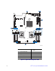
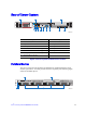
Back Panel Connectors
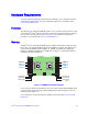
Figure 7. Back Panel Connectors
The NIC LEDs at the right and left of each NIC provide the following information.
A. NIC1 connector with USB
ports 2, 5
B. USB ports 8, 9
C. NIC2 connector D. RJ-45 Serial B port
E. Internal Video Connector
AF003217
A
B C D E
Table 3. NIC LED Descriptions
LED
LED
State
LED State Description
NIC1/
NIC2
Left
LED
Off No network connection
Solid Amber Network connection in place
Blinking Amber Transmit/receive activity
Right
LED
Off 10 Mbps connection (if left
LED is on or blinking)
Solid Amber 100 Mbps connection
Solid Green 1000 Mbps connection