Intel® Server System SR1690WB Service Guide A Guide for Technically Qualified Assemblers of Intel® Identified Subassemblies/ Products Intel Order Number E78186-004
Disclaimer Information in this document is provided in connection with Intel® products. No license, express or implied, by estoppel or otherwise, to any intellectual property rights is granted by this document.
Preface About this Manual Thank you for purchasing and using the Intel® Server System SR1690WB. This manual is written for system technicians responsible for troubleshooting, upgrading, and repairing this server board. This document provides a brief overview of the features of the board/chassis, a list of accessories or other components you may need, troubleshooting information, and instructions on how to add and replace components on the Intel® Server System SR1690WB.
Product Contents The Intel® Server System SR1690WB ships with the Intel® Server Board S5500WB. For further information, see the following documents: • Intel® Server Board S5500WB Technical Product Specification • Intel® Server System SR1690WB Technical Product Specification The contents of the server system are listed below.
• Operating system • For information about which accessories, memory, processors, and third-party hardware were tested and can be used with your board, and for ordering information for Intel products, see: http://support.intel.com/support/motherboards/server/ S5500WB/compat.
vi Intel® Server System SR1690WB Service Guide
Safety Information Important Safety Instructions Read all caution and safety statements in this document before performing any of the instructions. See also Intel Server Boards and Server Chassis Safety Information on the Intel® Server Deployment Toolkit CD and/or at http://support.intel.com/support/ motherboards/server/sb/cs-010770.htm. Wichtige Sicherheitshinweise Lesen Sie zunächst sämtliche Warnund Sicherheitshinweise in diesem Dokument, bevor Sie eine der Anweisungen ausführen.
Warnings Heed safety instructions: Before working with your server product, whether you are using this guide or any other resource as a reference, pay close attention to the safety instructions. You must adhere to the assembly instructions in this guide to ensure and maintain compliance with existing product certifications and approvals. Use only the described, regulated components specified in this guide.
Contents Preface ........................................................................................................................ iii About this Manual ................................................................................................................. iii Manual Organization ............................................................................................................. iii Product Contents ...................................................................................
Chapter 3: Hardware Installations and Upgrades ..................................................25 Before You Begin ................................................................................................................ 25 Tools and Supplies Needed ........................................................................................ 25 System References .....................................................................................................
Replacing the Backup Battery .............................................................................................56 Replacing the Power Supply ................................................................................................57 Removing the Power Supply .......................................................................................57 Installing the Power Supply .........................................................................................
Other Markings ............................................................................................................ 98 Regulated Specified Components ............................................................................... 99 End-of-Life / Product Recycling ................................................................................. 100 Appendix F: Warranty .............................................................................................
Décharges électrostatiques (ESD) ............................................................................123 Autres risques ............................................................................................................123 Périphériques laser ....................................................................................................124 Español ..............................................................................................................................
xiv Intel® Server System SR1690WB Service Guide
List of Figures Figure 1. Intel® Server System SR1690WB .............................................................................. 3 Figure 2. Cable Routing ............................................................................................................ 8 Figure 3. System Components.................................................................................................. 8 Figure 4. Server Board Connector and Component Locations ...............................................
Figure 43. Installing the backplane board ............................................................................... Figure 44. Removing the Server Board .................................................................................. Figure 45. Installing the Server Board .................................................................................... Figure 46. Replacing the Backup Battery ............................................................................... Figure 47.
List of Tables Table 1. Server System References ......................................................................................... 1 Table 2. Intel® Server System SR1690WB Feature Summary ................................................. 3 Table 3. NIC LED Descriptions ...............................................................................................15 Table 4. Control Panel LED Functions ....................................................................................17 Table 5.
xviii Intel® Server System SR1690WB Service Guide
1 Server System References If you need more information about this product or information about the accessories that can be used with this server system, use the following resources. Table 1. Server System References For this information or software For in-depth technical information about the server system, including sub-system overviews and mechanical drawings Use this Document or Software Intel® Server System SR1690WB Technical Product Specification can be found at: http://support.intel.
Table 1. Server System References For this information or software For drivers Use this Document or Software Driver (for an extensive list of drivers available) Operating System Driver (for operating system drivers) http://support.intel.com/support/motherboards/server/S5500WB/ For firmware and BIOS updates Firmware Update can be found at: For diagnostics test software Diagnostics: Platform Confidence Test (PCT) http://support.intel.com/support/motherboards/server/S5500WB/ Found at: http://support.
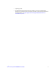
2 Server System Features This chapter briefly describes the main features of the Intel® Server System SR1690WB. This chapter provides illustrations of the product, a list of the server system features, and diagrams showing the location of important components and connections on the server system. al tic e Op evic D AF003210 Figure 1. Intel® Server System SR1690WB Table 2 summarizes the features of the server system. Table 2.
Table 2. Intel® Server System SR1690WB Feature Summary Feature Processor Description • • Memory Capacity Support for one or two Intel® Xeon® Processor 5500 series and Intel® Xeon® Processor 5600 series processors in FC-LGA 1366 Socket B package with up to 95 W Thermal Design Power (TDP). Supports future processor compatibility guidelines 4.8 GT/s, 5.86 GT/s, and 6.4 GT/s Intel® Quick Path Interconnect (Intel® QPI). Meets EVRD11.1 Expandable to 64 GB maximum.
Table 2. Intel® Server System SR1690WB Feature Summary Feature On-board Video Description On-board Server Engines* LLC Pilot II Controller Matrox* G200 2D Video Graphics controller Uses 8 MB of the BMC 32 MB DDR2 Memory LAN Support Two 10/100/1000 ports provided by Intel® 82576 with Intel® I/O Acceleration Technology (I/OAT) System Power Single 650-W power supply, 80 plus silver with PFC System Management On-board Server Engines* LLC Pilot II Controller.
Cable Routing When you add or remove components from your server system, make sure your cables are routed correctly before reinstalling the server system cover. Use caution to make sure no cables or wires are pinched and that the airflow from the fans is not blocked. Use the following figures to determine the correct cable routing for the SR1690WB system.
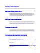
RAID Module Battery Backup Unit Power Supply Backplane Optical Drive Fan Modules Power from BBU to RAID Module H H SES cable from RAID Module to Backplane I Main Power J Aux.
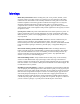
Figure 2. Cable Routing Chassis Component Identification This section helps you identify the components of your server system. If you are near the system, you can also use the Quick Reference Label provided on the inside of the chassis cover to assist in identifying components. Internal Components F G H E D C B A I al tic e Op evic D K J A AF003211 A. Rack handles (two) G. PCI Express* x16 riser B. Front Control Panel H. Mother board C. Hot swap backplane I. 650W power supply unit D.
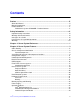
Server Board Connector and Component Locations A B C D E F G H PP OO NN MM I LL KK JJ II HH GG J K L EE CC AA Y X FF DD BB Z U W V S Q O M T R P N AF003212 Description Description A. Dual Intel® I/O Expansion Module Connectors W. 8-pin CPU Connector B. PCI Express* x16 Gen2 X. Processor Socket 2 C. Remote Management Module 3 Y. 4-pin Fan Connector (CPU2) D. POST Code LEDs Z. 4-pin Fan Connector (CPU2A) E. External I/O AA. 4-pin Fan Connector (MEM2) F. USB Connector BB.
Description Description G. Battery CC. DIMM Slot D2 H. SATA Connectors 0~5 DD. DIMM Slot D1 I. 24-pin Power Connector EE. DIMM Slot E1 J. N/A FF. DIMM Slot F1 K. Aux Power (5-pin or 7-pin) GG. Front Panel Connector L. RAID Key HH. HDD LED Header M. DIMM Slot C1 II. Low-Profile USB Connector N. DIMM Slot B1 JJ. Internal VGA Connector O. DIMM Slot A1 KK. N/A P. DIMM Slot A2 LL. USB Connector Q. 8-pin Fan Connector (MEM1R) MM. Slot 1 PCI Express* x8 Gen2 R.
Configuration Jumpers J6A3 E J6A2 F DCD to DTR Internal External DSR to DTR ME BMC Update J7A2 A BMC Force Update J1B5 A D Normal Update Password Clear J1C2 B B Normal C Clear Password BIOS Recovery Mode J1C3 C Normal Recovery J1B4 D Normal Reset BIOS AF003049 Intel® Server System SR1690WB Service Guide 11
Jumper Name J8C1: BMC Force Update Pins What happens at system reset... 1-2 BMC Firmware Force Update Mode Disabled (Default) 2-3 BMC Firmware Force Update Mode Enabled 1-2 Normal System Operation (Default) 2-3 Administrator and user passwords are cleared on the next reset 1-2 Normal System Operation (Default) 2-3 The main system BIOS will not boot with these pins jumpered. Note: the system boots from EFI-bootable recovery media with a recovery BIOS image.
Intel® Light Guided Diagnostics The server system contains numerous LEDs providing the following functions: • The System Status LED on the front and back panels (see Figure 6) shows the overall health of the system (green, blinking green, blinking amber, and off). • The System Identification LED on the back panel (see Figure 6) helps identify the server from among several servers. By default, the ID LED is off, and blue when activated by button or software.
A B C D G E FLT_F FLT_D1 FLT_E FLT_D2 FLT_A2 FLT_B FLT_A1 FLT_C F AF003216 A. Diagnostic LED B. System Status LED C. System ID LED D. 5V Standby LED E. CPU1 DIMM fault LEDs F. Fan Fault LEDs G. CPU2 DIMM fault LEDs Figure 6.
Back Panel Connectors A B C D E AF003217 A. NIC1 connector with USB ports 2, 5 B. USB ports 8, 9 C. NIC2 connector D. RJ-45 Serial B port E. Internal Video Connector Figure 7. Back Panel Connectors The NIC LEDs at the right and left of each NIC provide the following information. Table 3.
RAID Support The Intel® Server Board S5500WB provides an integrated SATA II host controller that supports independent DMA operation on the six Ports and supports data transfer rates of up to 3.0 Gb/Sec. The ICH10R provides support for Intel® Matrix Storage Technology, providing both AHCI and integrated RAID functionality. The industry-leading RAID capability provides high-performance RAID 0, 1, 5 and 10 functionality on up to six SATA ports.
Front Panel of Server System Standard Control Panel The following diagram shows the features of the standard control panel. A B C D E F G H I AF003218 Item Feature A. Power/Sleep Button B. System Reset Button C. Power/Sleep LED D. System NIC 1 Activity LED E. System NIC 2 Activity LED F. System Identification LED G. System Status LED H. System Identification Button I. USB 2.0 connectors – Port 0 & 1 Figure 8. Front Control Panel - Intel® Server System SR1690WB . Table 4.
Table 4. Control Panel LED Functions LED System ID System Status Color Blue State Description On Identify Active via command or button Off No Identification Green On System Ready / No Alarm Green Blink System ready, but degraded: redundancy lost such as the power supply or fan failure; non-critical temp/ voltage threshold; battery failure; or predictive power supply failure.
Rear of Server System A B N C D L M K J I H G F E AF003220 A. AC Power Receptacle I. RJ-45 Serial B port B. NIC 1 connector J. NIC2 Connector C. Top Cover Release Screw K. USB port 9 D. PCI Express* Add-in Card L. USB port 8 E. IO module external connector 2 (optional) M. USB port 5 F. IO module external connector 1 (optional) N. USB port 2 G. Management Network Interface (optional) H. Internal Video Connector Figure 9.
A. Front Control Panel B. Slimline Optical Drive C. Hard Drive Bays HDD0~3 D. HDD Status LED E. HDD Power LED Figure 10. Optional Peripherals Hard Disk Drives The server system ships with four hot-swap drive carriers for installing four SATA/SAS Hard disk drives, both 3.5-inch or 2.5-inch HDDs. For instructions on installing hard drives, see “Installing and Removing a Hot-swap Hard Drive” on page -35.
Hardware Requirements To avoid integration difficulties and possible board damage, your system must meet the requirements outlined below. For a list of qualified components, see the links under “Server System References”. Processor The Intel® Server System SR1690WB supports one or two Intel® Xeon® Processor 5500 series and Intel® Xeon® Processor 5600 series with 95W Thermal Design Power (TDP) or less and with a max data transfer rate of 6.4 GT/s.
Figure 12. Channel Slots Configuration The Independent Channel Mode is the default Maximum Performance Mode preferred for Intel® Xeon® Processor 5500 series and Intel® Xeon® Processor 5600 series based platforms. All three channels may be populated in any order and have no matching requirements. All channels must run at the same interface frequency, but individual channels may run at different DIMM timings (RAS latency, CAS latency, and so forth).
See the Intel® Server System S5500WB Technical Product Specification for additional information regarding the memory sub-system. Power Supply TThe Power supply in SR1690WB system provides 650W at maximum. The power supply must provide a minimum of 2.6 A of 5V standby current or the board will not boot. Optional Hardware Intel® RAID Activation Key If RAID 5 is needed, you can install the optional Intel® RAID Activation Key AXXRAKSW5.
Intel® I/O Expansion Module The Intel® Server System SR1690WB supports a variety of I/O Module options using 2x4 PCI Express* Gen2 Intel® I/O Expansion Module connectors on the rear of the server board. It accommodates both the double-wide I/O expansion modules and the PCI Express* Gen 1 I/O modules. Below is the list of supported I/O modules on SR1690WB: Table 5.
3 Hardware Installations and Upgrades Before You Begin Before working with your server product, pay close attention to the “Safety Information” at the beginning of this manual. Note: Whenever you service the system, you must first power down the server and unplug all peripheral devices and the AC power cord.
4. Slide the cover back until it stops and then lift the cover upward to remove it. See letter “C”. B C A al tic e Op evic D AF003222 Figure 13. Removing the Server System Cover Installing the System Cover 1. Observe the safety and ESD precautions at the beginning of this book. See “Safety Information”. 2. Place the cover over the server system so that the side edges of the cover sit just inside the server system sidewalls. Slide the cover forward (see letter “A” in Figure 14). 3.
B A C al tic e Op evic D AF003223 Figure 14. Installing the Server System Cover Removing and Installing the Processor Air Duct The system requires the use of an air duct to direct airflow and sustain appropriate air pressure. Always operate your server system with the air duct in place. The air duct is required for proper airflow within the server system. Removing the Processor Air Duct 1. Observe the safety and ESD precautions at the beginning of this book. See “Safety Information”. 2.
al tic e Op evic D AF003224 Figure 15. Removing the Processor Air Duct Installing the Processor Air Duct 1. Observe the safety and ESD precautions at the beginning of this book. See “Safety Information”. 2. Power down the server and unplug all peripheral devices and the AC power cable. 3. Remove the server system cover. For instructions, see “Removing the System Cover”. 4.
al tic e Op evic D AF003225 Figure 16. Installing the Processor Air Duct Installing and Removing Memory The silkscreen on the board for the DIMMs displays DIMM_A1, DIMM_A2, DIMM_B1, and DIMM_B2, DIMM_D1, DIMM_D2, DIMM_E1, and DIMM_E2 starting from the inside of the board. For two slots per channel configurations, the server board requires DDR3 DIMMs within a channel to be populated starting with the DIMM farthest from the processor. The DIMM farthest from the processor per channel is in blue on boards.
5. Remove the cover from the server and locate the DIMM sockets (see Figure 17). C E D B A AF003227 Figure 17. Installing the Memory 6. Make sure the clips at either end of the DIMM socket(s) are pushed outward to the open position (see letter “A” in Figure 17). 7. Holding the DIMM by the edges, remove it from its anti-static package. 8. Position the DIMM above the socket. Align the two small notches in the bottom edge of the DIMM with the keys in the socket (see letter “B” in Figure 17). 9.
7. Reinstall and reconnect any parts you removed or disconnected to reach the DIMM sockets. 8. Replace the server's cover and reconnect the AC power cord. Installing or Replacing the Processor Note: Use the following instructions to install or replace a processor instead of using the instructions that came with the processor. Caution: Processor must be appropriate: If you install a processor that is inappropriate for your server, you may damage the server board.
A B AF003229 Figure 19. Open the Load Plate 7. Remove the socket protective cover (see Figure 19). 8. Take the processor out of the box and remove the protective shipping cover (Figure 20). AF003292 Figure 20.
Note: Do not touch the socket pins; they are very sensitive and easily damaged. 9. Align the processor cutouts to match the two socket pins, and then insert the processor into the socket as shown in Figure 21. B A AF003293 Figure 21. Aligning the Processor 10. Close the load plate (see the letter “A” in Figure 22), close the socket lever and ensure the load plate tab engages under the socket lever when fully closed. (See letter “B” and “C” in Figure 22) C A B AF003294 Figure 22.
Installing the Heat Sink(s) 1. If a protective film covers the thermal interface material (TIM) on the underside of the heat sink, remove the protective film. 2. Align heat sink fans to the front and back of the chassis for correct airflow. Airflow goes from front-to-back of chassis. 3. Each heat sink has four captive fasteners and should be tightened as shown. 4. Using a #2 Phillips* screwdriver, finger-tighten each fastener diagonally according to the white-circled numbers (see Figure 23). 5.
3. Remove the AC power cord from the server. 4. Remove the server's cover. 5. Unplug the processor fan cable from the server board. 6. Loosen the four captive screws on the corners of the heat sink. 7. Twist the heat sink slightly to break the seal between the heat sink and the processor. 8. Lift the heat sink from the processor. If it does not pull up easily, twist the heat sink again. Do not force the heat sink from the processor. Doing so could damage the processor. 9. Lift the processor lever. 10.
A B AF003302 Figure 24. Pulling out the back lever 3. Remove the hard drive from its wrapper and place it on an antistatic surface. 4. Set any jumpers and/or switches on the drive according to the drive manufacturer's instructions. 5. With the drive circuit-side down, position the connector end of the drive so that it is facing the rear of the drive carrier. 6. Align the holes in the drive to the holes in the drive carrier and attach it to the carrier with the screws that were attached to the drive blank.
A B AF003304 Figure 26. 3.5 HDD Installation 7. With the black lever in the fully open position, slide the drive assembly into the server system. The green latch at the front of the drive carrier must be to the right. Do not push on the black drive carrier lever until the lever begins to close by itself. 8. When the black drive carrier lever begins to close by itself, push on it to lock the drive assembly into place. A B AF003305 Figure 27.
Removing a SAS or SATA Hot-swap Hard Disk Drive 1. Press in on the green latch at the front of the hard drive carrier. and pull out on the black lever to slide the carrier from the server system. 2. Remove the four screws that attach the hard drive to the drive carrier. Lift the drive from the carrier and store the drive in an anti-static bag. 3. With the black lever in the fully open position, slide the drive carrier into the server system. The green latch must be to the right.
AF003311 Figure 28. Removing the Knockout in Bezel for Optical Opening 2. Obtain the optical drive, and the optical drive latch from system package. 3. Screw the latch to the optical drive, and plug in the composed SATA/SATA Power cable, which is shipped in system package. B A AF003312 Figure 29. Attaching the Brackets to the Optical Drive 4. Lead the SATA/SATA Power cable through the optical drive bay before inserting the drive.
5. Slide the optical drive assembly in through the front of the chassis, as shown by letter “A in the following figure. The assembly will automatically be locked if the drive assembly is in position. B A AF003313 6. Connect the SATA cable connector to SATA port 4 or 5 on server board. 7. Connect the SATA power connector to P6 connector from system power supply. B al tic e Op evic D A AF003314 Figure 30.
Removing a Slimline Optical Drive 1. Disconnect the SATA power from system power supply and SATA cable connector from server board. 2. Press the optical latch and slide the optical drive assembly out of the chassis. 3. Install slimline drive bay filler blank, if no optical drive installed. Installing and Removing the PCI Riser Assembly Removing the PCI Riser Assembly 1. Disconnect any cables attached to any add-in cards. 2. Grasp the riser assembly and pull up to release it from the system.
A B AF003323 Figure 32. Installing the PCI Riser Assembly 3. Press down uniformly until the two hooks on the rear of the PCI riser assembly engage the server system back panel slots. The riser card will seat into the matching socket on the server board. Ensure the riser card is fully seated. Installing and Removing a PCI Add-In Card The following instructions describe how to install and remove a PCI add-in card. Installing a PCI Add-In Card Peripherals and add-in cards are not included in your system.
A B C AF003324 Figure 33. Installing a PCI Card in a Riser Card 3. Insert the riser card with the attached PCI card into the PCI slot on the server board. Press firmly on the riser card until it is fully seated. Be sure to press down on the riser card, not on the PCI card. Caution: Press the riser card straight down into the slot. Tipping the riser card while installing into the slot may damage the riser card or slot on the server board. 4.
Removing and Installing the System Fans Caution: The system fans are NOT hot-swappable. Before removing or replacing, you must first take the server out of service, turn off all peripheral devices connected to the system, turn off the system by pressing the power button, and unplug the AC power cord from the system or wall outlet. Note: The fans that are integrated into the power supply cannot be replaced separately. If one of the fans in the power supply fails, you must replace the power supply.
B ti Op D A Fan 1 A Fan 2 Fan 3 1 2 3 Fan 4 4 AF003309 Figure 35. Replacing the system fans 2. Disconnect the two 4-pin or one 8-pin system fan cables from the server board. See letters “2” in the following figure. 3. Lift the failed fan from the module. 4. Remove the plastic screws from the failed fans and install them into the new fans.
AF003308 Figure 36. Remove the screws from the fans 5. Position the replacement fan so the connector on the fan is at the right and pointing down. 6. With the fan oriented correctly, insert the fan into the fan module (see letter “3”), and insert the fan cable into the matching connector on the server board. (see letter “2”).
A ti Op D B Fan 1 B Fan 2 Fan 3 1 2 3 Fan 4 4 AF003310 Figure 37. Inserting the fan into the fan module Installing and Removing the I/O Expansion Module(s) Installing the I/O Expansion Module(s) 1. Squeeze the sides of the I/O expansion module cover to disengage it from the server system back panel and remove it (see letter “A”).
al tic e Op evic D A AF003317 Figure 38. Installing the I/O Expansion Module(s) 2. Attach the standoffs to the server board (see letter “A”) and attach the I/O shield gasket to the module (see letter “B”). 3. Attach the I/O expansion module(s) to the server board (see letter “C”).
A C B al tic e Op evic D AF003318 Figure 39. Attaching the I/O Expansion Module(s) Removing the I/O Expansion Module(s) 1. Remove the I/O expansion module(s) from the server board (see letter “A”). 2. Remove the standoffs from the server board (see letter “B”). 3. Install the I/O expansion module cover into the system back panel (see letter “C”).
Installing and Removing the Intel® Remote Management Module 3 and the Intel® RMM 3 NIC Installing the Intel® RMM3 and Intel® RMM3 NIC 1. Squeeze the sides of the Intel®RMM3 NIC module cover to disengage it from the server system back panel and remove it (see letter “A”) A al tic e Op evic D AF003315 Figure 40. Installing the Intel® RMM3 and Intel® RMM3 NIC 2. Attach the bracket of Intel® RMM3 NIC module by two screws (see letter “A”). 3.
B A C al tic e Op evic D AF003316 Figure 41. Attach the Intel® RMM3 module to rear chassis Removing the Intel® RMM3 and Intel® RMM3 NIC Use the reverse steps to remove the Intel® RMM3 module 1. Remove the two screws from rear chassis to loosen Intel® RMM3 board (see letter “C”). 2. Plug out Intel® RMM3 NIC module cable from the server board (see letter “B”). 3. Install the Intel® RMM3 NIC module cover into the system back panel (see letter “A”).
Removing the Backplane Board 1. Disengage hard drives from the backplane board (see letter “A”). 2. Disconnect all cables from the backplane board. 3. Remove two screws on the top of backplane bracket (see letter “B”). 4. Pull out the backplane assembly vertically from the chassis (see letter “C”). B C al tic e Op evic D A AF003300 Figure 42. Removing the backplane board Installing the Backplane Board 1.
B A al tic e Op evic D C AF003301 Figure 43. Installing the backplane board Replacing the Server Board Removing the Server Board 1. Remove the system air duct. 2. If installed, remove the memory, processor heat sinks, and processors from the server. 3. If installed, remove the PCI riser assembly. 4. If installed, disconnect all SATA cables from the server board. 5. Disconnect the system fans cables from server board. 6. Disconnect all power cables coming from the power supply to the server board.
7. Remove the nine screws from the server board (see letter “A”) and lift the server board from the server system (see letter “B”). A B al tic e Op evic D AF003297 Figure 44. Removing the Server Board 8. Install the replacement server board. See “Installing the Server Board” on page -54. Installing the Server Board 1. Place the server board into the server system as shown in the following figure (see letter “A”). 2. Attach the server board with nine screws (see letter “B”).
B A al tic e Op evic D AF003298 Figure 45. Installing the Server Board 3. Re-connect all power cables coming from the power supply to the server board. 4. Re-connect the system fan cables to server board. 5. Re-connect all SATA cables to the server board. 6. Install the PCI riser assembly. 7. Install the memory, processor heat sinks, and processors. 8. Install the system air duct.
Replacing the Backup Battery The lithium battery on the server board powers the RTC for up to 10 years in the absence of power. When the battery starts to weaken, it loses voltage, and the server settings stored in CMOS RAM in the RTC (for example, the date and time) may be wrong. Contact your customer service representative or dealer for a list of approved devices. Warning: Danger of explosion if battery is incorrectly replaced.
1. Observe the safety and ESD precautions at the beginning of this book. 2. Turn off all peripheral devices connected to the server. Turn off the server. 3. Disconnect the AC power cord from the server. 4. Remove the server's cover and locate the battery. 5. Insert the tip of a small flat bladed screwdriver, or an equivalent, under the tab in the plastic retainer. Gently push down on the screwdriver to lift the battery. 6. Remove the battery from its socket. AF003299 Figure 46.
1. Disconnect all power supply cables including power at rear of chassis (see letter “A”). 2. Remove the three screws securing the power supply to the back panel (see letter “B”). A B B D C AF003319 Figure 47. Removing the Power Supply from the Server System 3. Lift the power supply up to clear the chassis tab (see letter “C”) and remove the power supply by sliding it out (see letter “D”). Installing the Power Supply 1.
2. Lower the front of the power supply into place behind the chassis tab (see letter “B”). D C C A B AF003320 Figure 48. Installing the Power Supply into the Server System 3. Secure the power supply to the back panel with three screws (see letter “C”). 4. Connect all cables, including the power at the rear of the chassis (see letter “D”). Installing and Removing the Rack Handles Installing the Rack Handles 1.
AF003326 Figure 49. Installing the Rack Handle 2. Repeat step 1 on the opposite side of the server. Removing the Rack Handles 1. Remove the three screws holding the rack handle in place, and remove the rack handle from the server system. AF003327 Figure 50.
4 Server Utilities Using the BIOS Setup Utility This section describes the BIOS Setup Utility options, which is used to change server configuration defaults. You can run the BIOS Setup with or without an operating system being present. See “Server System References” for a link to the Intel® Server Board S5500WB Technical Product Specification where you can find details about specific BIOS setup screens.
“Setup Menu Key Use” describes the keyboard commands you can use in the BIOS Setup menus. Table 6. Setup Menu Key Use Key to Press Description Pressing on any menu launches the general help window. Left and right arrows The left and right arrow keys are used to move between the major menu pages. The keys have no effect if a submenu or pick list is displayed. Up arrow Select Item up - The up arrow is used to select the previous value in a menu item's option list, or a value field pick list.
Table 6. Setup Menu Key Use Key to Press Description Save and Exit - Pressing causes the following message to display: Setup Confirmation Save Configuration changes and exit now? [Yes] [No] If “Yes” is selected and is pressed, all changes are saved and Setup is exited. If “No” is selected and is pressed, or if is pressed, the user is returned to where they were before was pressed without affecting any existing values.
Obtaining the Upgrade Download the BIOS image file to a temporary folder on your hard drive. See “Server System References” for a link to the update software. Note: Review the instructions and release notes provided in the readme file distributed with the BIOS image file before attempting a BIOS upgrade. The release notes contain critical information regarding jumper settings, specific fixes, or other information to complete the upgrade.
CMOS Clear J1B4 1-2: Default 2 3 2-3: Clear CMOS BMC Force Update J1B5 1-2: Default 2 3 2-3: Enabled Password Clear J1C2 1-2: Default 2 3 2-3: Password Clear AF003214 Figure 51. CMOS Recovery Jumper 4. Reconnect the AC power and power up the system. 5. When the system begins beeping, power it down and disconnect the AC power. 6. Return the CMOS Clear jumper to the spare location, covering pins 1 and 2. 7. Close the server chassis; reconnect the AC power and power up the system. 8.
4. Reconnect the AC power; power up the system. 5. Power down the system and disconnect the AC power. 6. Return the Password Reset jumper to the Password Protect position, covering pins 1 and 2. Reconnect AC power and power up the server. 7. The password is now cleared and you can reset it by going into the BIOS setup. CMOS Clear J1B4 1-2: Default 2 3 2-3: Clear CMOS BMC Force Update J1B5 1-2: Default 2 3 2-3: Enabled Password Clear J1C2 1-2: Default 2 3 2-3: Password Clear AF003214 Figure 52.
Appendix A: Technical Reference 650-W Single Power Supply Input Voltages • 100-127V at 47/63 Hz; 8.6 A max. • 200-240V at 47/63 Hz; 4.3 A max. 650-W Single Power Supply Output Voltages The following table lists the total wattage available from the power subsystem for each voltage. Ensure your loads do not exceed the combined total wattage of 650 W. For information about calculating the power usage for your configuration, see “Power Budget Tool.” Table 7.
System Environmental Specifications Table 8. System Environmental Specifications Temperature Non-operating -40 ° to +70 °C. Operating 10° C to 35° C (50° F to 90° F) with the maximum rate of change not to exceed 10° C per hour Humidity Non-operating 90% relative humidity (non-condensing) at 35°C. Shock Operating 2.
Appendix B: Intel® Server Issue Report Form Note: For the fastest service, please submit your form via the Internet.
Other (Vendor/Model):___________________________________________ DIMM Configuration DIMM A1 MB and Vendor / part number: __________________________________ DIMM A2 MB and Vendor / part number: __________________________________ DIMM B1 MB and Vendor / part number: __________________________________ DIMM C1 MB and Vendor / part number: __________________________________ DIMM D1 MB and Vendor / part number: __________________________________ DIMM D2 MB and Vendor / part number: ______________________________
Add-in Card, Peripheral, Video, NIC Check each box below as applicable, and provide the requested information: Peripheral or Peripheral Description, Driver Revision, IRQ #, I/O Base Address, and FW Peripheral Description Driver Revision IRQ Make/Model IRQ FW Revision # I/O Base Address FW Revision # PCI Express* Gen2 x8 On-board Video Add-in Video On-board NIC1 (10/ 100/1000Mb/s) On-board NIC2 (10/ 100/1000Mb/s) Intel® I/O Expansion Module Revision #NIC Hard Drive Information Drive Type (SATA/ SA
Complete Problem Description In the space below, provide a complete description of the steps used to reproduce the problem or a complete description of where the problem can be found. Please also include any details on troubleshooting already done.
Appendix C: LED Decoder During the system boot process, the BIOS executes a number of platform configuration processes, each of which is assigned a specific hex POST code number. As each configuration routine is started, the BIOS displays the POST code to the POST Code Diagnostic LEDs on the back edge of the server board. To assist in troubleshooting a system hang during the POST process, the Diagnostic LEDs can be used to identify the last POST process that was executed.
Table 9. POST Progress Code LED Example 8h 4h 2h 1h 8h 4h 2h 1h Status ON OFF ON OFF ON OFF ON OFF Results 1 0 1 0 1 1 0 0 Ah Ch • Upper nibble bits = 1010b = Ah; Lower nibble bits = 1100b = Ch; the two are concatenated as ACh. Table 10.
Table 10.
Table 10.
Table 10.
Table 10.
Table 10.
Table 10.
Table 10.
Table 10. Diagnostic LED POST Code Decoder 0xEDh 1 1 1 0 1 0 0 1 Transfer control to Boot Device Selection (BDS) 0xEEh 1 1 1 0 1 1 0 0 Calling Int 19. One beep unless silent boot is enabled.
Appendix D: Getting Help If you encounter an issue with your server system, follow these steps to obtain support: 1. Visit the following Intel support web page: http://support.intel.com/support/motherboards/server This web page provides 24x7 support when you need it to get the latest and most complete technical support information on all Intel Enterprise Server and Storage Platforms.
84 Intel® Server System SR1690WB Service Guide
Appendix E: Regulatory and Compliance Information Product Regulatory Compliance Warning: To ensure regulatory compliance, you must adhere to the assembly instructions in this guide to ensure and maintain compliance with existing product certifications and approvals. Use only the described, regulated components specified in this guide.
• CB Certificate & Report, IEC60950 (report to include all country national deviations) • GS Certification (Germany) • • • • GOST R 50377-92 - Certification (Russia) Ukraine Certification (Ukraine) CE - Low Voltage Directive 73/23/EEE (Europe) IRAM Certification (Argentina) Product EMC Compliance - Class A Compliance Note: Legally the product is required to comply with Class A emission requirements as it is intended for a commercial type market place.
• C-Tick Declaration of Conformity (Australia) • MED Declaration of Conformity (New Zealand) • BSMI Certification (Taiwan) • • • • • • GOST R Certification / Certification (Russia) KCC Certification (Korea) IRAM Certification (Argentina) Ecology Declaration (International) China RoHS Environmental Friendly Use Period Packaging & Product Recycling Marks Product Regulatory Compliance References The following table references Server Chassis Compliance and markings that may appear on the product.
Table 11. Product Regulatory Compliance References Compliance Regional Description Canada / USA Compliance Reference Compliance Reference Marking Example CSA 60950 – UL 60950-1 (Safety) Listing Industry Canada ICES-003 (Emissions) CANADA ICES-003 CLASS A CANADA NMB-003 CLASSE A FCC CFR 47, Part 15 (Emissions) CENELEC Europe This device complies with Part 15 of the FCC Rules.
Table 11.
Electromagnetic Compatibility Notices FCC Verification Statement (USA) This device complies with Part 15 of the FCC Rules. Operation is subject to the following two conditions: (1) this device may not cause harmful interference, and (2) this device must accept any interference received, including interference that may cause undesired operation. For questions related to the EMC performance of this product, contact: Intel Corporation 5200 N.E.
Industry Canada (ICES-003) Cet appareil numérique respecte les limites bruits radioélectriques applicables aux appareils numériques de Classe A prescrites dans la norme sur le matériel brouilleur: "Apparelis Numériques", NMB-003 édictee par le Ministre Canadian des Communications.
BSMI (Taiwan) The BSMI Certification number and the following warning is located on the product safety label which is located on the bottom side (pedestal orientation) or side (rack mount configuration). The BSMI Certification Marking and EMC warning is located on the outside rear area of the product. KCC (Korea) Following is the KCC certification information for Korea.
Rack Mount Installation Guidelines Anchor the equipment rack: The equipment rack must be anchored to an unmovable support to prevent it from falling over when one or more servers are extended in front of the rack on slides. You must also consider the weight of any other device installed in the rack. A crush hazard exists should the rack tilt forward which could cause serious injury.
Main DC power disconnect: You are responsible for installing a properly rated DC power disconnect for the server system. This mains disconnect must be readily accessible, and it must be labeled as controlling power to the server. The circuit breaker of a centralized DC power system may be used as a disconnect device when easily accessible and should be rated no more than 10 amps.
Product Ecology Compliance Intel has a system in place to restrict the use of banned substances in accordance with world wide product ecology regulatory requirements. The following is Intel's product ecology compliance criteria. Table 12. Product Ecology Compliance Compliance Regional Description California Compliance Reference CA. Lithium Perchlorate insert California Code of Regulations, Title 22, Division 4.5; Chapter 33: Best Management Practices for Perchlorate Materials.
Table 12. Product Ecology Compliance Compliance Regional Description Europe Compliance Reference Compliance Reference Marking Example Waste Electrical and Electronic Equipment (WEEE) Directive 2002/96/ EC – Mark applied to system level products only. European Directive 2002/95/ EC - None Required Restriction of Hazardous Substances (RoHS) Threshold limits and banned substances are noted below. • • Quantity limit of 0.
Table 12. Product Ecology Compliance Compliance Regional Description Compliance Reference Compliance Reference Marking Example Recycling Markings – Fiberboard (FB) and Cardboard (CB) are marked with international recycling marks. Applied to outer bulk packaging and single package.
Other Markings Table 13. Other Markings Compliance Description Stand-by Power Compliance Reference Compliance Refernece Markings Stand-by Power Warnings Applied to product if stand-by power switch is used. Multiple Power Cords Multiple Power Cords Warnings Applied to product if more than one power cord is used. English: This unit has more than one power supply cord. To reduce the risk of electrical shock, disconnect (2) two power supply cords before servicing.
Table 13. Other Markings Compliance Description Compliance Reference Ground Connection Ground Connection Warnings Compliance Refernece Markings Line1 : “WARNING:” Swedish on line2: “Apparaten skall anslutas till jordat uttag, när den ansluts till ett nätverk.” Finnish on line 3: “Laite on liitettävä suojamaadoituskoskettimilla varustettuun pistorasiaan.” English on line 4: “Connect only to a properly earth grounded outlet.
End-of-Life / Product Recycling Product recycling and end-of-life take-back systems and requirements vary by country. Contact the retailer or distributor of this product for information about product recycling and / or take-back.
Appendix F: Warranty Limited Warranty for Intel® Chassis Subassembly Products Intel warrants that the Products (defined herein as the Intel® chassis subassembly and all of its various components and software delivered with or as part of the Products) to be delivered hereunder, if properly used and installed, will be free from defects in material and workmanship and will substantially conform to Intel's publicly available specifications for a period of three (3) years after the date the Product was purchas
This Limited Warranty does not cover damages due to external causes, including accident, problems with electrical power, usage not in accordance with product instructions, misuse, neglect, alteration, repair, improper installation, or improper testing. Warranty Limitations and Exclusions These warranties replace all other warranties, expressed or implied including, but not limited to, the implied warranties of merchantability and fitness for a particular purpose.
• North America and Latin America To obtain warranty repair for the product, please go to the following Web site to obtain instructions: http://support.intel.com/support/ motherboards/draform.htm • In Europe and in Asia Contact your original authorized distributor for warranty service. Any replacement Product is warranted under this written warranty and is subject to the same limitations and exclusions for the remainder of the original warranty period.
104 Intel® Server System SR1690WB Service Guide
Appendix G: Installation/Assembly Safety Instructions Important Safety Instructions Read all caution and safety statements in this document before performing any of the instructions. See also Intel Server Boards and Server Chassis Safety Information on the Resource CD and/or at: http://support.intel.com/support/motherboards/server/sb/cs-010770.htm English SAFETY STEPS: Whenever you remove the chassis covers to access the inside of the system, follow these steps: 1.
Wichtige Sicherheitshinweise Lesen Sie zunächst sämtliche Warn- und Sicherheitshinweise in diesem Dokument, bevor Sie eine der Anweisungen ausführen. Beachten Sie hierzu auch die Sicherheitshinweise zu Intel-Serverplatinen und -Servergehäusen auf der Ressourcen-CD oder unter: http://support.intel.com/support/motherboards/server/sb/cs-010770.htm SICHERHEISMASSNAHMEN: Immer wenn Sie die Gehäuseabdeckung abnehmen um an das Systeminnere zu gelangen, sollten Sie folgende Schritte beachten: 1.
Consignes de sécurité Lisez attention toutes les consignes de sécurité et les mises en garde indiquées dans ce document avant de suivre toute instruction. Consultez Intel Server Boards and Server Chassis Safety Information sur le CD Resource CD ou bien rendez-vous sur le site: http://support.intel.com/support/motherboards/server/sb/cs-010770.htm CONSIGNES DE SÉCURITÉ -Lorsque vous ouvrez le boîtier pour accéder à l'intérieur du système, suivez les consignes suivantes: 1.
Instrucciones de seguridad importantes Lea todas las declaraciones de seguridad y precaución de este documento antes de realizar cualquiera de las instrucciones. Vea Intel Server Boards and Server Chassis Safety Information en el CD Resource y/o en: http://support.intel.com/support/motherboards/server/sb/cs-010770.htm INSTRUCCIONES DE SEGURIDAD: Cuando extraiga la tapa del chasis para acceder al interior del sistema, siga las siguientes instrucciones: 1.
Italiano PASSI DI SICUREZZA: Qualora si rimuovano le coperture del telaio per accedere all'interno del sistema, seguire i seguenti passi: 1. Spegnere tutti i dispositivi periferici collegati al sistema. 2. Spegnere il sistema, usando il pulsante spento/acceso dell'interruttore del sistema. 3. Togliere tutte le spine dei cavi del sistema dalle prese elettriche. 4. Identificare e sconnettere tutti i cavi attaccati ai collegamenti I/O od alle prese installate sul retro del sistema. 5.
110 Intel® Server System SR1690WB Service Guide
Appendix H: Safety Information English Server Safety Information This document applies to Intel® Server Boards, Intel® Server Chassis (pedestal and rackmount) and installed peripherals. To reduce the risk of bodily injury, electrical shock, fire, and equipment damage, read this document and observe all warnings and precautions in this guide before installing or maintaining your Intel® Server Product.
Indicates do not touch fan blades, may result in injury. Indicates to unplug all AC power cord(s) to disconnect AC power Please recycle battery Intended Application Uses This product was evaluated as Information Technology Equipment (ITE), which may be installed in offices, schools, computer rooms, and similar commercial type locations.
Deutsch Sicherheitshinweise für den Server Das vorliegende Dokument bezieht sich auf Intel® Serverplatinen, Intel® Servergehäuse (Standfuß und Rack) sowie installierte Peripheriegeräte. Es enthält Warnungen und Vorsichtsmaßnahmen zur Vermeidung von Gefahren durch Verletzung, Stromschlag, Feuer und Beschädigungen von Geräten. Lesen Sie diese Dokument daher sorgfältig, bevor Sie Ihr Intel® Serverprodukt installieren oder warten.
Weist darauf hin, daß das Anfassen des Gebläses zu Verletzungen führen kann. Bedeutet, alle Netzkabel abzuziehen und das Gerät von der Netzspannung zu trennen. Bereiten Sie bitte Batterie auf Zielbenutzer der Anwendung Dieses Produkt wurde in seiner Eigenschaft als IT-Gerät getestet, das in Büros, Schulen, Computerräumen und ähnlichen öffentlichen Räumlichkeiten installiert werden kann. Die Eignung dieses Produkts für andere Einsatzbereiche als IT (z. B.
Warnungen zu Netzspannung und Elektrizität Caution: Durch Betätigen der mit dem Standby-Symbol gekennzeichneten Netztaste wird das System NICHT vollständig vom Netz getrennt. Es sind weiterhin 5 V aktiv, solange das System eingesteckt ist. Um das System vollständig vom Strom zu trennen, muß das Netzkabel aus der Steckdose abgezogen werden. Das System verfügt möglicherweise über mehrere Netzkabel. Vergewissern Sie sich in diesem Fall, daß alle Netzkabel abgezogen sind.
Warnhinweise für den Systemzugang Caution: Um Verletzungen und Beschädigungen zu vermeiden, sollten Sie vor Arbeiten im Produktinneren folgende Sicherheitsanweisungen beachten: • Schalten Sie alle am Produkt angeschlossenen Peripheriegeräte aus. • Schalten Sie das System mit dem Netzschalter aus. • Trennen Sie das Gerät von der Stromquelle, indem Sie alle Netzkabel vom System bzw. aus der Steckdose ziehen. • Ziehen Sie alle Kabel und alle an das System angeschlossenen Telekommunikationsleitungen ab.
Sie müssen für die gesamte Rack-Einheit einen Netztrennschalter einrichten. Dieser Netztrennschalter muß leicht zugänglich sein und über eine Kennzeichnung verfügen, die besagt, daß er die Stromzufuhr zur gesamten Einheit steuert und nicht nur zu den Servern. Zur Vermeidung von Stromschlaggefahr müssen das Rack selbst und alle darin eingebauten Geräte ordnungsgemäß geerdet sein.
• Prüfen Sie, ob Kabel, Erweiterungskarten sowie weitere Komponenten ordnungsgemäß angebracht sind. • Befestigen Sie die Abdeckungen am Gehäuse des Produkts, wie in dessen Anleitung beschrieben. Laser-Peripheriegeräte oder -Komponenten Caution: Beachten Sie zur Vermeidung von Strahlung und Verletzungen die folgenden Hinweise: • Öffnen Sie keinesfalls das Gehäuse von Laser-Peripheriegeräten oder LaserKomponenten.
ATTENTION Indique la présence d’un risque pouvant entraîner des blessures physiques mineures ou endommager légèrement le matériel si la mise en garde n’est pas prise en compte. AVERTISSEMEN T Indique la présence d’un risque pouvant entraîner des blessures corporelles graves si l’avertissement n’est pas pris en compte. Indique un risque potentiel si les informations signalées ne sont pas prises en compte.
• Dans les régions sujettes aux orages magnétiques, nous vous recommandons de brancher votre système à un suppresseur de surtension et de déconnecter les lignes de télécommunication de votre modem pendant les orages. • Équipé d’une prise murale reliée à la terre. • Équipé d’un espace suffisant pour accéder aux cordons d’alimentation secteur, car ils servent de disjoncteur principal d’alimentation du produit.
niveaux dangereux de tension, de courant et d’énergie. Renvoyez-le au fabricant en cas de problème. Lorsque vous remplacez un bloc d’alimentation à chaud, débranchez le cordon du bloc d’alimentation en cours de remplacement avant de le retirer du serveur. Pour éviter tout risque d’électrocution, mettez le système hors tension et débranchez les cordons d’alimentation ainsi que les systèmes de télécommunication, réseaux et modems reliés au système avant d’ouvrir ce dernier.
• Mettez toutes les vis ou autres attaches de côté lorsque vous retirez les panneaux d’accès. Une fois que vous avez terminé d’accéder à l’intérieur du produit, refixez le panneau d’accès avec les vis ou attaches d’origine. • N’essayez pas d’accéder à l’intérieur du bloc d’alimentation. Il ne contient aucune pièce réparable. Renvoyez-le au fabricant en cas de problème.
Décharges électrostatiques (ESD) Attention:Les décharges électrostatiques (ESD) peuvent endommager les lecteurs de disque dur, les cartes et d’autres pièces. Il est fortement conseillé d’effectuer l’ensemble des procédures décrites à un poste de travail protégé contre les ESD.
Périphériques laser Attention:Pour éviter tout risque d’exposition aux rayonnements et/ou de dommage personnel: • N’ouvrez pas l’enceinte d’un périphérique laser. • Les périphériques laser ne sont pas réparables par l’utilisateur. • Retournez-les au fabricant en cas de problème. Español Información de seguridad del servidor Este documento se aplica a las tarjetas de servidor de Intel®, las carcasas de servidor de Intel® (montaje en bastidor y en pedestal) y los dispositivos periféricos.
Indica un riesgo potencial si no se tiene en cuenta la información indicada. Indica riesgo de descargas eléctricas que podrían causar lesiones graves o la muerte si no se siguen las instrucciones de seguridad. Indica componentes o superficies calientes. Indica que no se deben tocar las aspas de los ventiladores, ya que de lo contrario se podrían producir lesiones.
Manipulacién del equipo Reduzca el riesgo de daños personales o en el equipo: • Respete los requisitos de sanidad y seguridad laborales de su país cuando traslade y levante el equipo. • Utilice medios mecánicos u otros que sean adecuados al trasladar o levantar el equipo. • Para que el peso sea menor para manipularlo con más facilidad, extraiga los componentes que sean de fácil extracción.
Precaución: Para evitar descargas eléctricas o fuego, revise los cables de alimentación que usará con el producto tal y como se describe a continuación: • No intente modificar ni utilizar los cables de alimentación de CA si no son exactamente del modelo especificado para ajustarse a las tomas de corriente conectadas a tierra.
• Al reemplazar una fuente de alimentación de conexión en funcionamiento, desenchufe el cable de alimentación de la fuente de alimentación que va a reemplazar antes de extraerla del servidor. Precaución: Si el servidor se ha estado ejecutando, los procesadores y disipadores de calor estarán recalentados. A no ser que esté instalando o extrayendo un componente de conexión en funcionamiento, deje que el sistema se enfríe antes de abrir las cubiertas.
Descarga electrostática (ESD) Precaución: Las descargas electrostáticas pueden dañar las unidades de disco, las tarjetas y otros componentes. Recomendamos que realice todos los procedimientos en una estación de trabajo protegida contra descargas electrostáticas.
Enfriamiento y circulación de aire Precaución: El tendido de los cables debe realizarse cuidadosamente tal y como se le indica para reducir al mínimo los problemas de obstrucción de la ventilación y de refrigeración. Para conseguir una refrigeración y corriente de aire adecuadas, compruebe que cuando sistema esté funcionando, las cubiertas de la carcasa están instaladas. Si utiliza el sistema sin las cubiertas, podría dañar sus componentes.
简体中文 服务器安全信息 本文档适用于 Intel® 服务器主板、Intel® 服务器机箱(基座和机架固定件)和已安装的外设。为减少人身伤害、电击、火灾 以及设备毁坏的危险,请在安装或维护 Intel® 服务器产品之前阅读本文档并遵循本指南中的所有警告和预防措施。 如果本文档中的信息与特定产品的随附信息或 Web 站点信息之间存在不一致,请以产品文档为准。 服务器须由合格的技术人员进行集成和维护。 必须遵守本指南的规定和服务器手册的装配指导,以确保符合现有的产品认证和审 批。仅使用本指南中描述和规定的指定组件。使用其他产品 / 组件将使产品的 UL 认证和其他管理审批无效,并可能导致产品不符合销售地的产品法规。 安全警告与注意事项 为避免人身伤害与财产损失,安装本产品之前,请阅读以下所有安全指导和信息。 下面所列的安全符号可能在整个文档中使用并可能标注于产品和 / 或产品包装之上。 注意 表示如果无视此“? ? ? 项”? ? ? ? ? ? ? 轻微人身伤害或财产损失的危险。 警告 表示如果无视此“? ? ”? ? ? ? ? ? ? 严重人身伤害的危险。 表示如果无视所示信息,即存在潜在的危险。
预期应用使用 根据评估,本产品为信息技术设备 (ITE),可安装在办公室、学校、计算机房和类似的商业场所。本产品对于非 ITE 应用的其他产品种类和环境(如医疗、工业、住宅、报警系统和测试设备)的适用 性尚有待进一步的评估。 场地选择 本系统专为在典型办公环境运行而设计。请选择符合以下条件的地点: • • • • • • • 清洁、干燥,无气载微粒(而非一般的室内尘埃)。 通风良好,远离热源(包括直接日晒和散热器)。 远离振动源或物理震动。 与电气设备产生的强大电磁场隔离。 在易受闪电袭击的地区,我们建议将系统插入电涌抑制器并在闪电期间断开通信 线路与调制解调器之间的连接。 提供正确接地的墙壁插座。 提供足够的空间,以便拿取电源供应线,因为这是本产品的主要电源断开器。 设备操作规范 减少人身伤害或设备受损的危险: • • • 移举设备时遵守当地的职业健康与安全要求。 借助机械手段或其他合适的手段移举设备。 拆除一切易分离组件,以降低重量并方便操作。 电源与电气警告 注意事项 电源按钮(如待机电源标记所示)并不能完全关闭系统的交流电源,只要系统已接 通电源,就存在 5V 待机电源。要从系统切断电源,须
为避免电击,请在打开服务器之前,关闭服务器并断开服务器上连接的电源线、电 信系统、网络和调制解调器。 电源线警告 如果产品未提供交流电线,请购买一根您所在国家批准使用的交流电线。 注意事项 为避免电击或火灾危险,请按如下所述对产品所用的电源线进行检查: • • • • 若非所需的符合接地插座的确切类型,请勿尝试修改或使用交流电线 电源线须符合以下标准: ⎯ 电源线的电气额定值须大于产品上标注的电流额定值。 ⎯ 电源线须拥有适合插座的安全接地插头或触点。 电源线为交流电源的主要断开设备。插座须靠近设备并可随时断开。 电源线须插入所提供的拥有合适接地的插座。 系统使用警告 注意事项 为避免人身伤害或财产损失,无论何时检查产品内部,以下安全指导都适用: • • • • • • • • 关闭所有与本产品相连的外设。 按下电源按钮至关闭状态,关闭系统。 从系统或墙壁插座上拔下所有交流电线,断开交流电源。 断开与系统相连的所有线缆和通信线路。 卸除舱口盖时,保留所有螺钉及其他紧固件。完成产品内部检查之后,请 用螺钉或紧固件重新固定舱口盖。 请勿打开电源供应设备。电源供应设备内没有可维修部件。请与生产商联系 维
注意事项 为避免受伤,请勿触摸运转的风机叶片。如果系统的风机上配有防护装置,请勿卸 下风机防护装置运行系统。 机架固定件警告 设备的机架须固定在稳固的支座上,以防从中安装服务器或设备时倒塌。须按照机 架生产商提供的安装说明进行安装。 从下往上将设备安装在机架上,最重的设备安装在机架的最底层。 一次只从机架上安装一件设备。 您须负责安装整个机架装置的主要电源断开设备。此主要断开设备须随时可用,且 须标明为控制整个装置(而不仅限于服务器)的电源。 为避免潜在的电击危险,须对机架及其上所安装的每一件设备实行正确的安全接地 。 静电放电 (ESD) 注意事项 ESD 会损坏磁盘驱动器、主板及其他部件。我们建议您执行 ESD 工作站的所有步骤。如果没有 ESD 工作站,则采取一些静电放电保护措施,操作部件时,戴上与服务器上的机箱接地 或任何未喷漆金属表面连接的防静电腕带。 操作主板时始终保持小心。它们可能对 ESD 非常敏感。拿持主板时只接触边缘。从保护包装中或从服务器上取出主板后,请将 主板组件侧面朝上放置在无静电的接地表面上。请使用导电泡沫垫(若有),不要 使用主板包装。请勿将主板在任何表面上滑动。 134
其他危险 替换电池 注意事项 不正确替换电池可能导致爆炸危险。替换电池时,请只使用设备生产商推荐使用的 电池。 请按当地法规处置电池。 请勿对电池充电。 请勿拆卸、刺穿或以其他方式损坏电池。 冷却和气流 注意事项 按照说明小心布置线缆,尽量减少气流阻塞和冷却问题。 为保证适当的冷却和气流,运行系统时请确保机箱盖已安装。未安装机箱盖即运行 系统可能导致系统部件受损。安装机箱盖的步骤如下: • • • 首先检查并确保系统内没有遗留的未固定工具或部件。 检查线缆、内插板和其他组件已正确安装。 按产品说明安装机箱盖。 激光外设或激光设备 注意事项 为避免幅射暴露和 / 或人身伤害: • 请勿打开任何激光外设或激光设备的外壳 • 激光外设或激光设备为非用户维修设备 请与生产商联系维修事宜 Intel® Server System SR1690WB Service Guide 135
136 Intel® Server System SR1690WB Service Guide