
Datasheet


Connector / Header Locations and Pin-outs Intel® Server Board S5520HC / S5500HCV TPS
Revision 1.2
Intel order number E39529-009
108
6.3 System Management Headers
6.3.1 Intel
®
Remote Management Module 3 Connector
A 34-pin Intel
®
RMM3 connector (J1C1) is included on the server boards to support the optional
Intel
®
Remote Management Module 3. These server boards do not support third-party
management cards.
Note: This connector is not compatible with the Intel
®
Remote Management Module (Intel
®
RMM) or the Intel
®
Remote Management Module 2 (Intel
®
RMM2).
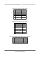
Table 50. Intel
®
RMM3 Connector Pin-out (J1C1)
Pin Signal Name Pin Signal Name
1 3V3_AUX 2 RMII_MDIO
3 3V3_AUX 4 RMII_MDC
5 GND 6 RMII_RXD1
7 GND 8 RMII_RXD0
9 GND 10 RMII_RX_DV
11 GND 12 RMII_REF_CLK
13 GND 14 RMII_RX_ER
15 GND 16 RMII_TX_EN
17 GND 18 KEY (pin removed)
19 GND 20 RMII_TXD0
21 GND 22 RMII_TXD1
23 3V3_AUX 24 SPI_CS_N
25 3V3_AUX 26 NC (spare)
27 3V3_AUX 28 SPI_DO
29 GND 30 SPI_CLK
31 GND 32 SPI_DI
33
GND
34
RMM3_Present_N (pulled high on baseboard
and shorted to ground on the plug-in module)
6.3.2 LCP / IPMB Header
Table 51. LCP / IPMB Header Pin-out (J1G6)
Pin Signal Name Description
1 SMB_IPMB_5VSB_DAT BMC IMB 5 V standby data line
2 GND Ground
3 SMB_IPMB_5VSB_CLK BMC IMB 5 V standby clock line
4 P5V_STBY +5 V standby power