
Datasheet


Intel® Server Boards S5520HC and S5500HCV TPS Connector / Header Locations and Pin-outs
Revision 1.2
Intel order number E39529-009
107
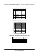
Table 47. CPU 1 Power Connector Pin-out (J9A1)
Pin Signal Color
1 GND of Pin 5 Black
2 GND of Pin 6 Black
3 GND of Pin 7 Black
4 GND of Pin 8 Black
5 +12 Vdc CPU1 Yellow / black
6 +12 Vdc CPU1 Yellow / black
7 +12 Vdc
DDR3_CPU1
Yellow / black
8 +12 Vdc
DDR3_CPU1
Yellow / black
Table 48. CPU 2 Power Connector Pin-out (J9K1)
Pin Signal Color
1 GND of Pin 5 Black
2 GND of Pin 6 Black
3 GND of Pin 7 Black
4 GND of Pin 8 Black
5
+12 Vdc CPU2
Yellow /
black
6
+12 Vdc CPU2
Yellow /
black
7 +12 Vdc
DDR3_CPU2
Yellow /
black
8 +12 Vdc
DDR3_CPU2
Yellow /
black
Table 49. Power Supply Auxiliary Signal Connector Pin-out (J9K2)
Pin Signal Color
1 SMB_CLK_FP_PWR_R Orange
2 SMB_DAT_FP_PWR_R Black
3 SMB_ALRT_3_ESB_R Red
4 3.3 V SENSE- Yellow
5 3.3 V SENSE+ Green