
Quick Start Guide Back Page

Side 2
17
Install Software
• BIOS, Drivers, and Operating System Install
A. Confirm BIOS Version:
Look on the Server/System Management screen in the BIOS Setup Utility to
determine the installed BIOS version.
Compare this to the versions at:
http://support.intel.com/support/motherboards/server/S5500BC/
If new versions are available, update the BIOS on your server. See the User Guide on the Intel
®
Server
Deployment Toolkit 3.0 CD for update instructions.
B. Configure your RAID Controller:
Use the instructions provided with the RAID controller.
C. Install your Operating System:
Use the instructions provided with the RAID controller and with
the operating system.
D. Install Operating System Drivers:
With the operating system running, insert the Intel
®
Server
Deployment Toolkit 3.0 CD. If using a Microsoft* Windows* operating system, the Express Installer will
autorun and allow you to select the appropriate drivers to install. On other operating systems, browse the
CD folders to locate and install the driver files.
15
Install Rack
Handles
Install Rail Kit
(optional)
See the documentation that came
with your selected rail kit for
installation instructions.
Front Panel Controls and Indicators
(shown with bezel removed)
A USB 2.0 Port
B. Power Button
C. Status LED
D. Power LED
E. HDD Activity
F. NIC1
G. NIC2
ABCDEFG
16
Finishing Up
Before installing your operating system, you must finish your system
installation and connect back panel I/O connectors and AC power.
CAUTION: This unit must
be operated with the TOP
COVER installed to ensure
proper cooling.
2. Connect your keyboard, mouse, video and other I/O cables/devices
as shown. Then connect the AC power cord.
1. Make sure you have replaced the system cover.
Network
NIC1-2
Serial
Port A
VGA
AC Power
PCIe*
USB 7, 9
USB 6,8
14
Install the Top Cover
B
Place cover onto
chassis and slide
forward.
Install two screws
at front.
C
Attach with one
screw at rear.
A
A
B
C
13
Install Processor Air Duct
Install processor air
duct as shown.
Use care to avoid
pinching system
cables.
11
Install PCI Add-in Card(s)
A
Remove filler panel from the add-in card slot.
B
Insert add-in card
until it seats in the
riser connector.
C
Secure add-in card
with screw as shown.
Add-in Card
CAUTION:
Observe normal
ESD precautions
when installing
add-in cards.
C
A
Riser Assembly
Supports one
PCIe* x8 card.
Ris
er
Card
Riser Connector
Filler Panel
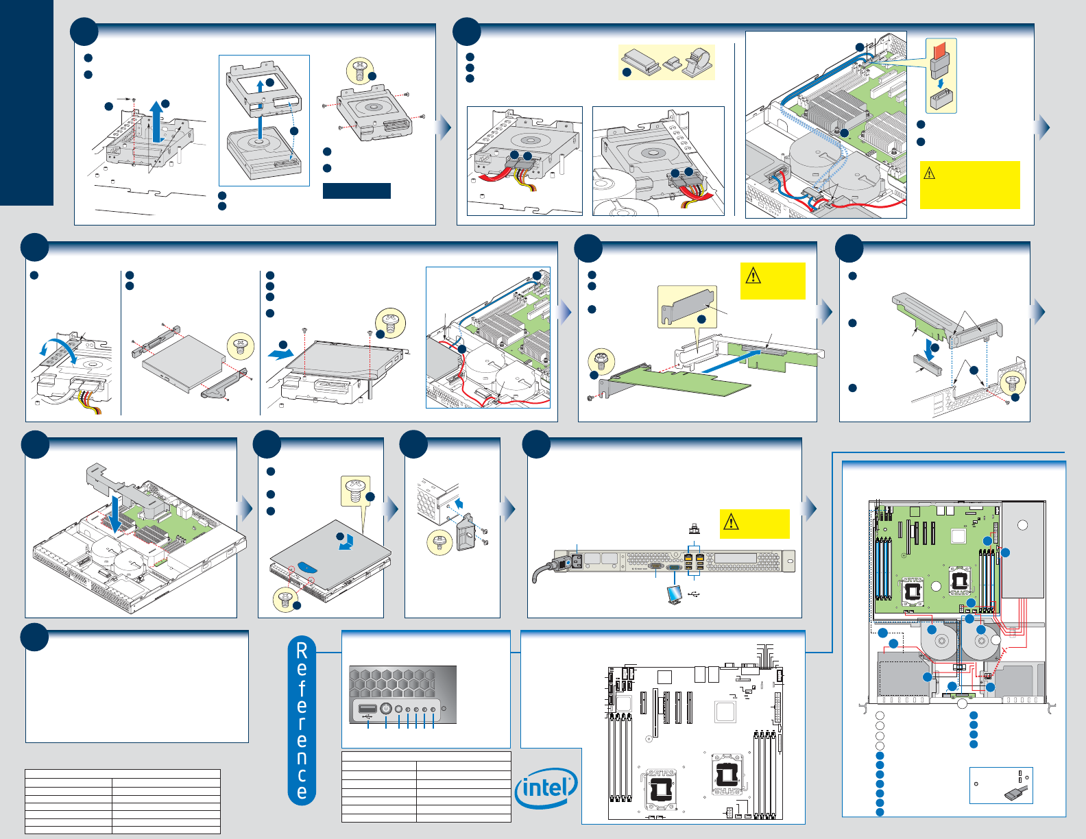
Server Board
S5500BC
Component
Layout
See your Intel
®
Server
Board S5500BC User's
Guide for expanded
component and
connection information.
ICH10
Note: Refer to the
Technical Product
Specification for
Diagnostic LED
decoder list.
Diagnostic LEDs
DIMM_A2
DIMM_A1
DIMM_B2
DIMM_B1
DIMM_E1
DIMM_E2
DIMM_D1
DIMM_D2
CPU 1 Socket
CPU 2 Socket
Slot 7 (PCI Express* x8)
Slot 6 (PCI Express* x8, Riser Card)
Slot 5 (PCI Express* x4)
Slot 4 (PCI 32/33)
RMM3
Slot 3 (PCI Express* x4)
NIC 2
USB 9
USB 8
NIC 1
USB 7
USB 6
VGA
Serial A
SYS FAN 3
SYS FAN 2
SATA 4
USB 2-3
USB 0-1
SATA 5
Serial B
HSBP_A
Main Power
CPU Power
BIT1
LSB
DIMM Fault
LEDs
Front Panel Header
CPU 1 FAN
SYS FAN 1 CPU 2 FAN
DIMM Fault LEDs
IOH
P/S AUX
SATA RAID
Key
Status LED
ID LED
BIT3
BIT2
BIT6
MSB
BIT4
BIT5
BMC
SATA 0
SATA 1
SATA 3
SATA 2
Battery
IPMB_1
SATA SGPIO
12
Install PCI Add-in Card Riser Assembly
A
Align the riser card with the server
board riser socket.
C
Secure the riser
assembly with
one screw at
rear of chassis.
B
Before pressing
into place, make
sure the two
hooks engage
the two slots
on the back
panel top edge.
PCI Riser
Riser
Socket
Tabs (2)
Slots (2)
Riser
Card
A
B
C
8
Install Hard Drives/Carriers
Repeat these steps for
each installed hard drive
B
Remove the screw securing the drive carrier to
the chassis.
Slide the carrier away from the two chassis
sidewall pins and remove.
A
F
Attach the hard drive to the carrier with
four screws as shown.
Re-install the hard drive/carrier assembly
into the chassis.
C
Insert hard drive into the carrier.
D
Make sure connector-end of drive
goes into the carrier as shown.
E
C
D
E
Screw
A
B
Sidewall Pins
9
Cabling Hard Drives
B
Attach a SATA power cable to each hard drive as shown.
Attach a SATA data cable to each hard drive as shown.
C
Use the cable clips provided with your chassis to maintain
proper air flow.
A
Left-side SATA 0 Hard Drive Right-side SATA 1 Hard Drive
B
A
Cable Clips
C
B
A
CAUTION It is critical that you connect
the SATA data cables correctly from the
hard drives to your server board.
Failure to do so may result in data loss.
Example: HDD 0 to server board SATA 0.
Server
Board
HDD
0
HDD
1
Fan
Module
1
Clips
E
D
0
E
Attach each SATA data cable to its matching
server board SATA connector as shown.
Route cables to server board as shown.
D
10
Install and Cable Optical Device (optional)
E
Insert optical device assembly into front panel opening.
Attach optical device tray to chassis standoff as shown.
F
Connect data ribbon cable to optical device and server
board SATA connector as shown.
G
Connect power cable.
D
D
E
B
Before installing the optical device,
you must remove the slimline bezel.
Remove by rocking back and forth
to break the attach points. Once
removed, this bezel cannot be
used again.
Attach the LEFT bracket to the optical device as shown.
C
Attach the RIGHT bracket to the optical device.
A
Slimline
Bezel
LEFT
Bracket
RIGHT
Bracket
Optical Device
Server
Board
F
Optical Device
Power Cable
Clip
G
Platform Cabling Diagram
HDD 0
HDD 1
Optical Device
B
C
D
F
I
K L
N
O
A
Server Board
B
Power Supply
C
Fan Module
D
Front Panel Board
F
Front Panel USB
G
HDD 0 to Server Board SATA 0
I
Front Panel
H
HDD 1 to Server Board SATA 1
J
Power to Server Board (Main)
K
Fan Module Power ... left fan
Server Board SATA
Connector Legend
L
Fan Module Power ... right fan
M
Power to Server Board (CPU)
N
Optical Device Data Cable
O
Optical Device Power
P
Auxiliary Signals for the Power Supply
1
0
Begin cable
connections at
the SATA-0
location.
CPU 2
CPU 1
0
2
A
H
J
M
P
G
1
543
Document Type
Available Documents
Technical Product Specification
Spares and Configuration Guide
Tested Hardware and Operating System List
Tested Memory List
Tested Processor List
Software and Drivers
Content
In-depth technical information
Supported accessories and spares list
Tested peripherals and operating systems list
Tested memory list
Supported processors list
Up-to-date firmware, driver and utility information
Additional reference documents available a
t:
http://support.intel.com
400 W Power Supply
Optional Accessories/Spares and Order Codes
Chassis Blower and Fan Kit
Fixed Chassis Product Maintenance Kit
PCIe* (LP) Riser Card
AXXSATADVDROM
Tool-less Rail Kit
Cable Management Arm
FHJT400WPS
FHJBLOWER
FHJTFIXPMKIT
AHJTPCIERISER
AXXSATADVDROM
AXXHERAIL
AXXRACKCARM
A complete list of accessories and spares can be found at
:
http://support.intel.com