Intel® Server System SC5650BCDP Technical Product Specification Intel order number: E80367-002 Revision 1.
Intel® Server System SC5650BCDP TPS Revision History Revision History Date Revision Number Modifications August 2009 1.0 Initial Release March 2010 1.5 Adding support for Intel® Xeon® processors 5600 series ii Intel order number: E80367-002 Revision 1.
Intel® Server System SC5650BCDP TPS Disclaimers Disclaimers Information in this document is provided in connection with Intel® products. No license, express or implied, by estoppel or otherwise, to any intellectual property rights is granted by this document.
Table of Contents Intel® Server System SC5650BCDP TPS Table of Contents 1. 2. 3. Introduction .......................................................................................................................... 1 1.1 Server Board Use Disclaimer .................................................................................. 1 1.2 Server Board Use Disclaimer .................................................................................. 1 Product Overview..................................
Intel® Server System SC5650BCDP TPS 5.3 5.3.1 6. Table of Contents Hot Swap Hard Disk Drive Bays ............................................................................ 34 Fixed Hard Drive Bay............................................................................................. 34 Standard Control Panel ..................................................................................................... 36 6.1 Control Panel ...................................................................
List of Figures Intel® Server System SC5650BCDP TPS List of Figures Figure 1. Intel® Server System SC5650BCDP.............................................................................. 4 Figure 2. Intel® Server System SC5650BCDP Components ........................................................ 5 Figure 3. ATX 2.2 I/O Aperture ..................................................................................................... 6 Figure 4. Intel® Server Board S5500BC picture ...........................
Intel® Server System SC5650BCDP TPS List of Tables List of Tables Table 1. System Feature Set ........................................................................................................ 2 Table 2. Intel® Server System SC5650BCDP Dimensions ........................................................... 4 Table 3. Intel® Server System SC5650BCDP Components Reference ........................................ 5 Table 4. Board Layout reference ..........................................................
List of Tables Intel® Server System SC5650BCDP TPS Table 32. System Environmental Limits Summary ..................................................................... 39 Table 33. System Maintenance Procedure Times ...................................................................... 40 Table 34. Product Safety & Electromagnetic (EMC) Compliance ............................................... 42 Table 35. Product Ecology Compliance Reference Table .........................................................
Intel® Server System SC5650BCDP TPS List of Tables < This page intentionally left blank. > Revision 1.
Intel® Server System SC5650BCDP TPS Introduction 1. Introduction This Technical Product Specification (TPS) provides system specific information detailing the features, functionality, and high level architecture of the Intel® Server System SC5650BCDP. You should also reference the Intel® Server Board S5500BC Technical Product Specification for more details regarding the functionality and architecture specific to the integrated server board and what is supported in this server system.
Intel® Server System SC5650BCDP TPS Product Overview 2. Product Overview The Intel® Server System SC5650BCDP is a 5U server system which integrates the Intel® Server Board S5500BC into the Intel® Server Chassis SC5650DP. The server system features are designed to support the high-density server market. This chapter provides a high-level overview of the system features. Greater detail for each major system component or feature is provided in the following chapters. Table 1.
Intel® Server System SC5650BCDP TPS Feature Add-in PCI, PCI Express* Cards Product Overview Description Slot6: One half-length (6.6 inches) PCI Express* Gen2 x8 connector with X8 link width Slot7 : One half-length (6.6 inches) PCI Express* Gen2 x8 connector with x8 link width Slot5 : One half-length (6.6 inches) PCI Express* Gen2 x8 connector with x4 link width Slot3 : One half-length (6.6 inches) PCI Express* x4 connector with x4 link width Slot4 : One half-length (6.
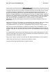
Intel® Server System SC5650BCDP TPS Product Overview Feature Server Management Description On-board ServerEngines* LLC Pilot II Controller Integrated Baseboard Management Controller (Integrated BMC), IPMI 2.0 compliant Integrated Super I/O on LPC interface ® Support for Intel Server Management Software System Management 2.1 ® Intel System Management Software System Views Figure 1. Intel® Server System SC5650BCDP 2.2 System Dimensions Table 2.
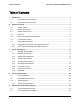
Intel® Server System SC5650BCDP TPS 2.3 Product Overview System Components Figure 2. Intel® Server System SC5650BCDP Components Table 3. Intel® Server System SC5650BCDP Components Reference A Description Control panel controls and indicators B Description Two half-height 5.25-in peripheral drive bays C Internal hard drive bay cage (behind door) D Security lock E USB ports(two) F 120-mm system fan Revision 1.
Intel® Server System SC5650BCDP TPS Product Overview G Description Hard drive cage retention mechanism H Description Alternate external SCSI knockout I Fixed Hard drive fan J Alternate serial B port knockout K Padlock loop L PCI card guide (PCI fan behind ) M External SCSI knockout N Serial B port knockout O Power supply (fixed power supply shown) P AC input power connector Q I/O shield R PCI Add-in board slots 2.
Intel® Server System SC5650BCDP TPS Product Overview Figure 4. Intel® Server Board S5500BC picture Revision 1.
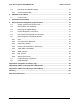
Intel® Server System SC5650BCDP TPS Product Overview 2.7.1 Server Board Connector and Component Layout The following figure shows the board layout of the server board. Each connector and major component is identified by a number or letter, and is described in Table 4.. Figure 5. Intel® Server Board S5500BC Layout Table 4. Board Layout reference A SATA 3 Description B Description Internal dual port USB2.
Intel® Server System SC5650BCDP TPS Product Overview Description Description Q System fan 3 header R Main power connector S DIMM sockets for Channel A & B (Supports CPU_1) T Power Supply Auxiliary Connector U SSI 24-pin Front Panel connector V System fan 2 header W CPU_1 fan header X CPU Power Connector Y CPU_1 Socket Z Intel® IOH 5500 chipset AA CPU Socket 2 BB CPU 2 fan header CC System fan 1 header DD DIMM sockets for Channels D and E (Supports CPU_2) EE SATA SGPIO FF S
Intel® Server System SC5650BCDP TPS Product Overview Table 5. Intel® Light-Guided Diagnostic LED reference 10 A Description Post-Code Diagnostic LEDs B Description Status LED C System ID LED D HDD LED E System Fan 3 Fault LED F 5 VSB LED G DIMM Fault LED H System Fan 2 Fault LED I CPU 1 Fan Fault LED J CPU 2 Fan Fault LED K System Fan 1 Fault LED L DIMM Fault LED Intel order number: E80367-002 Revision 1.
Intel® Server System SC5650BCDP TPS Power Sub-System 3. Power Sub-System 3.1 600-Watt Power Supply The 600-W power supply specification defines a non-redundant power supply that supports the Intel® server systems SC5650BCDP. The 600-W power supply has eight outputs: 3.3V, 5V, 12V1, 12V2, 12V3, 12V4, -12V and 5VSB. This form factor fits into a pedestal system and provides a wire harness output to the system. An IEC connector is provided on the external face for AC input to the power supply.
Intel® Server System SC5650BCDP TPS Power Sub-System 3.1.1 Mechanical Overview Figure 7. Mechanical Drawing for Power Supply Enclosure 12 Intel order number: E80367-002 Revision 1.
Intel® Server System SC5650BCDP TPS 3.1.2 Power Sub-System Airflow and Temperature The power supply incorporates one 80-mm fan for self and system cooling. The fan provides no less than 14 CFM of airflow through the power supply when installed in the system. The cooling air enters the power module from the non-AC side. The power supply operates within all specified limits over the Top temperature range. Table 6. Thermal Environmental Requirements ITEM DESCRIPTION Operating temperature range.
Intel® Server System SC5650BCDP TPS Power Sub-System Figure 8. Output Cable Harness for 600-W Power Supply NOTES: 1. ALL DIMENSIONS ARE IN MM 2. ALL TOLERANCES ARE +10 MM / -0 MM 3. INSTALL 1 TIE WRAP WITHIN 12MM OF THE PSU CAGE 4. MARK REFERENCE DESIGNATOR ON EACH CONNECTOR 5. TIE WRAP EACH HARNESS AT APPROX. MID POINT 6. TIE WRAP P1 WITH 2 TIES AT APPROXIMATELY 15M SPACING. 14 Intel order number: E80367-002 Revision 1.
Intel® Server System SC5650BCDP TPS Power Sub-System Table 7.
Intel® Server System SC5650BCDP TPS Power Sub-System Contact: Molex* 39-00-0059 or equivalent Table 9. P2 Processor 0 Power Connector Pin Signal 18 AWG Color Pin Signal 18 AWG Color 1 COM Black 5 +12V1 White 2 COM Black 6 +12V1 White 3 COM Black 7 +12V1 Brown 4 COM Black 8 +12V1 Brown 3.1.3.3 P3 Processor 1 Power Connector Connector housing: 8- Pin Molex* 39-01-2085 or equivalent Contact: Molex* 39-00-0059 or equivalent Table 10.
Intel® Server System SC5650BCDP TPS 1 2 3 4 3.1.3.6 +12V4 COM COM +5Vdc Power Sub-System Blue/White Stripe Black Black RED P9 Right-angle SATA Power Connector Connector Housing: JWT* F6002HS0-5P-18 or equivalent Contact: Table 13. P9 Right-angle SATA Power Connector Pin 1 2 3 4 5 3.1.3.7 Signal +3.3V Ground +5V Ground +12V4 18 AWG Color Orange Black Red Black Green P10 SATA Power Connector Connector Housing: 5-pin Molex* 67926-0011 or equivalent Contact: Molex* 67926-0041 or equivalent Table 14.
Intel® Server System SC5650BCDP TPS Power Sub-System Table 15. AC Input Rating PARAMETER MIN Rated 140 Vrms Max Input Current 10 A1,3 200-240 Vrms 264 Vrms 5 A2,3 50/60Hz 63 Hz Voltage (110) 90 Vrms 100-127 Vrms Voltage (220) 180 Vrms Frequency 47 Hz MAX Start up VAC 85Vac +/4Vac Power Off VAC 75Vac +/5Vac Notes: Maximum input current at low input voltage range shall be measured at 90VAC, at max load.
Intel® Server System SC5650BCDP TPS 3.1.4.5 Power Sub-System AC In-rush AC line in-rush current does not exceed a 50A peak, cold start @ 20 degrees C and no damage @ hot start for up to one-quarter of the AC cycle, after which, the input current is no more than the specified maximum input current at 264Vac input. The peak in-rush current is less than the ratings of its critical components (including input fuse, bulk rectifiers, and surge limiting device).
Intel® Server System SC5650BCDP TPS Power Sub-System 3.1.4.8 AC Line Fast Transient (EFT) Specification The power supply meets the EN 61000-4-5 directive and any additional requirements in IEC1000-4-5:1995 and the Level 3 requirements for surge-withstand capability, with the following conditions and exceptions: • These input transients do not cause any out-of-regulation conditions, such as overshoot and undershoot, nor do they cause any nuisance trips of any of the power supply protection circuits.
Intel® Server System SC5650BCDP TPS Power Sub-System The remote sense return (ReturnS) is able to regulate out a minimum of 200mV drop in the power ground return. The current in any remote sense line is less than 5mA to prevent voltage sensing errors. The power supply operates within specification over the full range of voltage drops from the power supply’s output connector to the remote sense points. 3.1.5.
Intel® Server System SC5650BCDP TPS Power Sub-System 3.1.5.6 Voltage Regulation The power supply output voltages are within the following voltage limits when operating at steady state and dynamic loading conditions. These limits include the peak-peak ripple/noise. All outputs are measured with reference to the return remote sense signal (ReturnS). The +12V3, +12V4, –12V and 5VSB outputs are measured at the power supply connectors referenced to ReturnS. The +3.
Intel® Server System SC5650BCDP TPS 3.1.5.8 Power Sub-System Capacitive Loading The power supply is stable and meets all requirements with the following capacitive loading ranges. Table 21. Capacitive Loading Conditions 3.1.5.9 Output MIN MAX Units +3.
Intel® Server System SC5650BCDP TPS Power Sub-System Table 22. Ripple and Noise +3.3V 50mVp-p 3.1.5.13 +5V 50mVp-p +12V(1,2,3,4) 120mVp-p -12V 120mVp-p +5VSB 50mVp-p Timing Requirements The timing requirements for power supply operation are as follows. The output voltages must rise from 10% to within regulation limits (Tvout_rise) within 5 to 70ms, except for 5VSB which is allowed to rise from 1.0 to 25ms. The +3.3V, +5V and +12V output voltages start to rise at approximately the same time.
Intel® Server System SC5650BCDP TPS Power Sub-System Vout V1 10% Vout V2 V3 V4 Tvout rise Tvout_off Tvout_on Figure 9. Output Voltage Timing Table 24. Turn On / Off Timing Item Tsb_on_delay Description Delay from AC being applied to 5VSB being within regulation. Minimum Maximum Units 1500 msec Tac_on_delay Delay from AC being applied to all output voltages being within regulation. 2500 msec Tvout_holdup Time all output voltages stay within regulation after loss of AC.
Intel® Server System SC5650BCDP TPS Power Sub-System AC Input Tvout_holdup Vout Tpwok_low TAC_on_delay Tsb_on_delay Tpwok_on PWOK 5VSB Tpwok_off Tsb_on_delay Tpwok_on Tpwok_off Tpson_pwok Tpwok_holdup T5VSB_holdup Tsb_vout Tpson_on_delay PSON AC turn on/off cycle PSON turn on/off cycle Figure 10. Turn On/Off Timing (Power Supply Signals) 3.1.6 Protection Circuits Protection circuits inside the power supply cause only the power supply’s main outputs to shut down.
Intel® Server System SC5650BCDP TPS Power Sub-System Table 25. Over Current Protection (OCP) VOLTAGE 3.1.7.1 +3.3V Min 26.4A OVER CURRENT LIMIT Max 36A +5V 26.4A 36A +12V1 18A 20A +12V2 18A 20A +12V3 18A 20A +12V4 18A 20A -12V 0.625A 4A 5VSB N/A 8A Over Voltage Protection (OVP) The power supply over voltage protection is locally sensed. The power supply will shut down and latch off after an over voltage condition occurs.
Intel® Server System SC5650BCDP TPS Power Sub-System 3.1.7.3 PSON# Input Signal The PSON# signal is required to remotely turn on/off the power supply. PSON# is an active low signal that turns on the +3.3V, +5V, +12V, and -12V power rails. When this signal is not pulled low by the system, or left open, the outputs (except the +5VSB) turn off. This signal is pulled to a standby voltage by a pull-up resistor internal to the power supply.
Intel® Server System SC5650BCDP TPS Signal Type Power Sub-System Open collector/drain output from power supply. Pull-up to VSB located in system. Power OK PWOK = High PWOK = Low Power Not OK Logic level low voltage, Isink=4mA Logic level high voltage, Isource=200μA MIN MAX 0V 0.4V 2.4V 5.25V Sink current, PWOK = low 4mA Source current, PWOK = high 2mA PWOK delay: Tpwok_on 100ms PWOK rise and fall time Power down delay: T pwok_off 3.1.
Intel® Server System SC5650BCDP TPS Cooling Sub-System 4. Cooling Sub-System 4.1 Fan Configuration The cooling sub-system of the Intel® Server System SC5650BCDP consists of one 120mm chassis fan, one 120mm PCI fan and one 92mm drive bay fan. The 4-wire chassis fan provides cooling at the rear of the chassis by drawing fresh air into the chassis from the front and exhausting warm air out the system. This fan is PWM controlled.
Intel® Server System SC5650BCDP TPS Cooling Sub-System Figure 12. Cooling Fan Configuration for Intel® Server Board S5500BC The Intel® Server System SC5650BCDP is engineered to provide sufficient cooling for all internal components of the server. The cooling subsystem is dependent upon proper airflow. The designated cooling vents on both the front and back of the chassis must be left open and must not be blocked by improperly installed devices.
Intel® Server System SC5650BCDP TPS Cooling Sub-System The pin configuration for each fan connector is identical. The following table provides pin-out information. Table 29. CPU and System Fan Connector Pin-out (Location: J3K1, J7K2, J3K2, J8K3, J8B4) Pin 1 32 Signal Name Ground Type GND Description GROUND is the power supply ground. 2 12V Power Power supply 12 V. 3 Fan Tach Out FAN_TACH signal is connected to the BMC to monitor the fan speed.
Intel® Server System SC5650BCDP TPS Peripheral and Hard Drive Support 5. Peripheral and Hard Drive Support The following sections describe the components shown in the figure below: Figure 13: Front View Components (without Front Bezel Assembly) Table 30: Front View Components Reference Description 5.1 A 5.25-in Device Drive Bays B 3.5-in Device Drive Bay C Hard Drive Cage D Drive Bay EMI Shield (shown open) E Front Panel USB Ports 3.
Peripheral and Hard Drive Support Intel® Server System SC5650BCDP TPS peripherals can be up to 9 inches (228.6 mm) deep. As a guideline, the maximum recommended power per device is 17W. Thermal performance of specific devices must be verified to ensure compliance to the manufacturer’s specifications. The 5.25-in peripherals can be inserted and removed without tools from the front of the chassis after taking off the access cover and removing the front bezel.
Intel® Server System SC5650BCDP TPS Peripheral and Hard Drive Support Figure 14: Fixed Hard Drive Bay Intel® Server System SC5650BCDP is capable of accepting a single SAS/SATA hot swap backplane hard drive enclosure in place of the fixed drive bay. Both backplanes (expanded and non-expanded) have a connector to accommodate a SAF-TE controller on an add-in card. Each backplane type supports up to six 1-in hot swap drives when mounted in the docking drive carrier. Revision 1.
Intel® Server System SC5650BCDP TPS Standard Control Panel 6. Standard Control Panel The Intel® Server System SC5650BCDP control panel configuration has three buttons and five LEDs. When the hot-swap drive bay is installed, a bi-color hard drive LED is located on each drive carrier (six totals) to indicate specific drive failure or activity. These LEDs are visible upon opening the front bezel door. 6.1 Control Panel The control panel buttons and LED indicators are displayed in the following figure.
Intel® Server System SC5650BCDP TPS Standard Control Panel Table 31. Control Panel LED Functions LED Name Power/Sleep LED LAN # 1Link/Activity Color Green Green LAN # 2Link/Activity Green Hard drive activity Green Status LED Green Amber Revision 1.
Intel® Server System SC5650BCDP TPS PCI Cards and Assembly 7. PCI Cards and Assembly The Intel® Server Board S5500BC integrated into this system provides five PCI slots: • Slot3: One half-length (6.6 inches) PCI Express* x4 connector with x4 link width • Slot4: One half-length (6.6 inches) 5-V PCI 32 bit / 33 MHz connector • Slot5: One half-length (6.6 inches) PCI Express* Gen2 x8 connector with x4 link width • Slot6: One half-length (6.
Intel® Server System SC5650BCDP TPS Environmental and Regulatory Specifications 8. Environmental and Regulatory Specifications 8.1 System Level Environmental Limits The following table defines the system level operating and non-operating environmental limits. Table 32.
Environmental and Regulatory Specifications Intel® Server System SC5650BCDP TPS Table 33. System Maintenance Procedure Times Activity Remove cover 8.
Intel® Server System SC5650BCDP TPS 8.4 Environmental and Regulatory Specifications Product Regulatory Compliance The server chassis product, when correctly integrated per this guide, complies with the following safety and electromagnetic compatibility (EMC) regulations. Intended Application – This product was evaluated as Information Technology Equipment (ITE), which may be installed in offices, schools, computer rooms, and similar commercial type locations.
Environmental and Regulatory Specifications Intel® Server System SC5650BCDP TPS The following table references Server Chassis Compliance and markings that may appear on the product. Markings below are typical markings however, may vary or be different based on how certification is obtained. Table 34.
Intel® Server System SC5650BCDP TPS Compliance Regional Description Environmental and Regulatory Specifications Compliance Reference Japan VCCI Certification Korea RRL Certification MIC Notice No. 1997-41 (EMC) & 1997-42 (EMI) Russia GOST-R Certification GOST R 29216-91 (Emissions) GOST R 50628-95 (Immunity) Ukraine Ukraine Certification Taiwan BSMI CNS13438 Compliance Reference Marking Example 인증번호: CPU-Model Name (A) None Required R33025 Revision 1.
Environmental and Regulatory Specifications 8.6 8.6.1 Intel® Server System SC5650BCDP TPS Electromagnetic Compatibility Notices USA This device complies with Part 15 of the FCC Rules. Operation is subject to the following two conditions: (1) this device may not cause harmful interference, and (2) this device must accept any interference received, including interference that may cause undesired operation. For questions related to the EMC performance of this product, contact: Intel Corporation 5200 N.E.
Intel® Server System SC5650BCDP TPS 8.6.2 Environmental and Regulatory Specifications FCC Verification Statement Product Type: SR1630; S5500BC This device complies with Part 15 of the FCC Rules. Operation is subject to the following two conditions: (1) This device may not cause harmful interference, and (2) this device must accept any interference received, including interference that may cause undesired operation.
Environmental and Regulatory Specifications 8.6.6 Intel® Server System SC5650BCDP TPS BSMI (Taiwan) The BSMI Certification number and the following warning is located on the product safety label which is located on the bottom side (pedestal orientation) or side (rack mount configuration). 8.6.7 RRL (Korea) Following is the RRL certification information for Korea. English translation of the notice above: 1. 2. 3. 4. 5. 8.6.8 Type of Equipment (Model Name): On License and Product Certification No.
Intel® Server System SC5650BCDP TPS Environmental and Regulatory Specifications Table 35. Product Ecology Compliance Reference Table Compliance Regional Description Compliance Reference California California Code of Regulations, Title 22, Division 4.5; Chapter 33: Best Management Practices for Perchlorate Materials. China China RoHS Administrative Measures on the Control of Pollution Caused by Electronic Information Products” (EIP) #39. Referred to as China RoHS.
Environmental and Regulatory Specifications Compliance Regional Description Intel® Server System SC5650BCDP TPS Compliance Reference European Directive 2002/95/EC Restriction of Hazardous Substances (RoHS) Threshold limits and banned substances are noted below. Quantity limit of 0.1% by mass (1000 PPM) for: Lead, Mercury, Hexavalent Chromium, Polybrominated Biphenyls Diphenyl Ethers (PBB/PBDE) Quantity limit of 0.
Intel® Server System SC5650BCDP TPS 8.8 Environmental and Regulatory Specifications Other Markings Compliance Description Stand-by Power Compliance Reference Compliance Reference Marking Example 60950 Safety Requirement Applied to product is stand-by power switch is used. . Multiple Power Cords 60950 Safety Requirement Applied to product if more than one power cord is used.
Appendix A: Integration and Usage Tips Intel® Server System SC5650BCDP TPS Appendix A: Integration and Usage Tips This section provides a list of useful information unique to the Intel® Server System SC5650BCDP that you should keep in mind while integrating the server system. 50 • The Intel® Server System SC5650BCDP requires the use of a shielded LAN cable to comply with Immunity regulatory requirements. • You must use the system air duct to maintain system thermals.
Intel® Server System SC5650BCDP TPS Appendix B: POST Code Diagnostic LED Decoder Appendix B: POST Code Diagnostic LED Decoder The BIOS executes platform configuration processes during the system boot. Each process is assigned a specific hex POST code number. As each configuration routine is started, the BIOS displays the POST code on the POST Code Diagnostic LEDs on the back edge of the server board. The Diagnostic LEDs identify the last POST process to be executed.
Appendix B: POST Code Diagnostic LED Decoder Intel® Server System SC5650BCDP TPS Table 37. Diagnostic LED POST Code Decoder Diagnostic LED Decoder O = On, X=Off Checkpoint Upper Nibble Lower Nibble Description MSB LSB 8h 4h 2h 1h 8h 4h 2h 1h LED #7 #6 #5 #4 #3 #2 #1 #0 Multi-use code – This POST Code is used in different contexts.
Intel® Server System SC5650BCDP TPS Appendix B: POST Code Diagnostic LED Decoder Diagnostic LED Decoder O = On, X=Off Checkpoint Upper Nibble Lower Nibble MSB LSB 8h 4h 2h 1h 8h 4h 2h 1h LED #7 #6 #5 #4 #3 #2 #1 #0 0x51h X O X O X X X O 0x52h X O X O X X O X 0x53h X O X O X X O O 0x54h X O X O X O X X 0x55h X O X O X O X O 0X56h X O X O X O O X 0x57h X O X O X O O O USB 0x58h X O X O O X X X 0x59h X O X O O X X O ATA/ATAPI/SATA 0x5Ah X O X O O X O X 0x5Bh X O X O O X O O SMBUS 0x5Ch X O X O O O X X 0x5Dh
Appendix B: POST Code Diagnostic LED Decoder Intel® Server System SC5650BCDP TPS Diagnostic LED Decoder O = On, X=Off Checkpoint Upper Nibble Lower Nibble Description MSB LSB 8h 4h 2h 1h 8h 4h 2h 1h LED #7 #6 #5 #4 #3 #2 #1 #0 0xD3 O O X O X X O O Trying to boot device selection 3 0xD4 O O X O X O X X Trying to boot device selection 4 0xD5 Trying to boot device selection 5 X O X O O O X O 0xD6 O O 0Xd7 O O 0xD8 O O O X O O X Trying to boot device selection 6 X O X O O O Trying to boot
Intel® Server System SC5650BCDP TPS Appendix C: POST Error Messages and Handling Appendix C: POST Error Messages and Handling Whenever possible, the BIOS outputs the current boot progress codes on the video screen. Progress codes are 32-bit quantities plus optional data. The 32-bit numbers include class, subclass, and operation information. The class and subclass fields point to the type of hardware being initialized. The operation field represents the specific initialization activity.
Appendix C: POST Error Messages and Handling Intel® Server System SC5650BCDP TPS Error Code 0195 Error Message Processor 0x Intel(R) QPI speed mismatch. Response Major 0196 Processor 0x model mismatch. Fatal 0197 Processor 0x speeds mismatched. Fatal 0198 Processor 0x family is not supported. Fatal 019F Processor and chipset stepping configuration is unsupported.
Intel® Server System SC5650BCDP TPS Appendix C: POST Error Messages and Handling Error Code 854B DIMM_F2 Disabled. Error Message Response Major 8560 DIMM_A1 Component encountered a Serial Presence Detection (SPD) fail error. Major 8561 DIMM_A2 Component encountered a Serial Presence Detection (SPD) fail error. Major 8562 DIMM_B1 Component encountered a Serial Presence Detection (SPD) fail error. Major 8563 DIMM_B2 Component encountered a Serial Presence Detection (SPD) fail error.
Intel® Server System SC5650BCDP TPS Appendix C: POST Error Messages and Handling Error Code 9506 Error Message ATA/ATPI component encountered a controller error. Response Minor 95A6 PCI component encountered a controller error. Minor 95A7 PCI component encountered a read error. Minor 95A8 PCI component encountered a write error. Minor 9609 Unspecified software component encountered a start error. Minor 9641 PEI Core component encountered a load error.
Intel® Server System SC5650BCDP TPS Appendix C: POST Error Messages and Handling In case of POST error(s) listed as Major, the BIOS enters the error manager and waits for the user to press an appropriate key before booting the operating system or entering the BIOS Setup. The user can override this option by setting the POST Error Pause option as disabled on the BIOS setup Main screen. If this option is disabled, the system boots the operating system without user intervention. The default is disabled.
Intel® Server System SC5650BCDP TPS Glossary Glossary Word / Acronym ACA Australian Communication Authority Definition ANSI American National Standards Institute BMC Baseboard Management Controller CMOS Complementary Metal Oxide Silicon D2D DC-to-DC EMP Emergency Management Port FP Front Panel FRB Fault Resilient Boot FRU Field Replaceable Unit LCD Liquid Crystal Display LPC Low-Pin Count MTBF Mean Time Between Failure MTTR Mean Time to Repair OTP Over-temperature Protection O
Intel® Server System SC5650BCDP TPS Reference Documents Reference Documents • Intel® Server Board S5500BC Technical Product Specification • Intel® Server Chassis SC5650 Technical Product Specification • Intel® Server Board S5500BC / Intel® Server Chassis SC5650 / Intel® Server System SR1630BC Spares/Parts List and Configuration Guide • Intel® S5500 Chipsets Server Board BIOS External Product Specification Revision 1.