
Product Service Guide


18 Intel
®
Server Board S5500BC User’s Guide
b. Proceed to the screw at location 2 and loosen it by giving it two rotations and
stop.
c. Loosen screws at locations 3 and 4 by giving each screw two rotations and then
stop.
d. Repeat steps 1a through 1c by giving each screw two rotations each time until all
screws are loosened.
2. Lift the heatsink from the board.
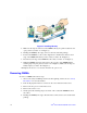
3. Remove and discard the spacer (see letter "C" in Figure 1).
Note: The system is shipped with a spacer installed between the heatsink and the processor
socket to protect the socket protective cover. You must remove and discard this spacer
before installing the processor.
Installing the Retention Mechanism(s) and Heatsink(s)
You must install the processor before installing the heatsink. For instructions, refer to the
User/Service Guide for your server. For instructions on replacing a processor, refer to the
next section, “Replacing a Processor”.
Caution: The heatsink has Thermal Interface Material (TIM) located on the bottom of it. Use
caution when you unpack the heatsink so you do not damage the TIM.
Note: New unused heatsinks have adequate TIM on the bottom. If you are reusing a heatsink
from replacing a processor, make sure there is adequate TIM present on the heatsink to
support processor cooling.
To install the heatsink, follow these steps:
1. Remove the protective film on the TIM if present.
2. Orient the heatsink over the processor as shown in Figure 1. You must position the
heatsink fins as shown to provide correct airflow through the system.
3. Set the heatsink over the processor, lining up the four captive screws with the four
posts surrounding the processor.
4. Loosely screw in the captive screws on the heatsink corners in a diagonal manner
according to the numbers shown in Figure 1 as follows:
a. Starting with the screw at location 1, engage the screw threads by giving it two
clockwise rotations and stop. (IMPORTANT: Do NOT fully tighten.)
b. Proceed to the screw at location 2 and engage the screw threads by giving it two
rotations and stop.
c. Engage screws at locations 3 and 4 by giving each screw two rotations and then
stop.
d. Repeat steps 4a through 4c by giving each screw two rotations each time until all
screws are lightly tightened upto a maximum of 8 inch-lbs torque.