
Product Service Guide


Intel
®
Server Board S5500BC User’s Guide 17
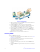
9. Align the processor cutouts to match the two socket pins, and then insert the
processor into the socket as shown in Figure 12.
Figure 12. Installing the Processor
10. Close the load plate (see the letter “A” in Figure 13), close the socket lever and
ensure the load plate tab engages under the socket lever when fully closed. (See
letter “B” and “C” in Figure 13)
Figure 13. Close the Load Plate and Socket Lever
Note: Make sure the alignment triangle mark and the alignment triangle cutout align correctly.
To assist in package orientation and alignment with the socket:
Removing the Heatsink(s)
To remove the heatsink, follow these steps:
1. Loosen the four captive screws on the heatsink corners in a diagonal manner
according to the numbers shown in Figure 1 as follows:
a. Starting with the screw at location 1, loosen it by giving it two counterclockwise
rotations and stop. (IMPORTANT: Do NOT fully loosen.)