
Product Service Guide


Intel® Server System SC5650BCDP Service Guide 23
2 Hardware Installations and Upgrades
This document provides instructions for adding and replacing chassis components. For
instructions on replacing components on the server board, such as the processor and
memory DIMMs, see the instructions provided with the server board.
Before You Begin
Before working with your server product, review the important safety information listed
in Appendix G, “Safety Information”.
Tools and Supplies Needed
• Phillips* (cross head) screwdriver (#1 bit and #2 bit)
• Needle-nosed pliers
• Anti-static wrist strap and conductive foam pad (recommended)
• Hex nut driver (6 mm)
System References
All references to the left, right, front, top, and bottom assume the reader is facing the front
of the chassis as it would be positioned for pedestal operation.
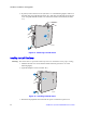
Removing and Installing the Left Side Cover
Warning: This chassis must be operated with the left side cover installed to ensure proper cooling.
Removing the Left Side Cover
The Intel
®
Server System SC5650BCDP must be operated with the left side cover in place
to ensure proper cooling. You must remove the left side cover to add or replace
components inside of the platform. Before removing the left side cover, power down the
server and unplug all peripheral devices and the AC power cable.
Note: You may need a non-skid surface or a stop behind the chassis to prevent the chassis from
sliding on your work surface.
1. Observe the safety and ESD precautions listed in Appendix G, “Safety Information”.
2. Turn off all peripheral devices connected to the server. Turn off the server.
3. Disconnect the AC power cord(s).