
Technical Product Specification
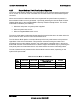
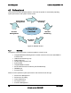


Table Of Contents
- 1. Introduction
- 2. Product Overview
- 3. Functional Architecture
- 3.1 Processor Support
- 3.1.1 Processor Population Rules
- 3.1.2 Multiple Processor Initialization
- 3.1.3 Enhanced Intel SpeedStep® Technology
- 3.1.4 Intel® Extended Memory 64 Technology (Intel® EM64T)
- 3.1.5 Execute Disable Bit Feature
- 3.1.6 Multi-Core Processor Support
- 3.1.7 Intel® Virtualization Technology
- 3.1.8 Platform Environmental Control Interface (PECI)
- 3.1.9 Common Enabling Kit (CEK) Design Support
- 3.2 Intel® 5400 Memory Controller Hub Chipset (Intel® 5400 MCH Chipset)
- 3.2.1 Processor Front-Side Buses
- 3.2.2 Snoop Filter
- 3.2.3 System Memory Controller and Memory Subsystem
- 3.2.3.1 Supported Memory
- 3.2.3.2 DIMM Population Rules and Supported DIMM Configurations
- 3.2.3.3 Minimum Memory Configuration
- 3.2.3.4 Memory upgrades
- 3.2.3.5 ECC Code Support
- 3.2.3.6 Memory Sparing
- 3.2.3.7 FBD Memory Thermal Management
- 3.2.3.8 BIOS Support of Memory Subsystem
- 3.2.3.9 Memory Error Handing
- 3.2.3.10 Memory Error Reporting
- 3.3 Intel® 6321ESB I/O Controller Hub
- 3.4 PCI Subsystem
- 3.4.1 Intel® 6321ESB I/O Controller Hub PCI32: 32-bit, 33-MHz PCI Bus Segment
- 3.4.2 Intel® 6321ESB I/O Controller Hub Port 1: x4 PCI Express* Bus Segment
- 3.4.3 Intel® 6321ESB I/O Controller Hub Port 2: x4 PCI Express* Bus Segment
- 3.4.4 MCH to Intel® 6321ESB I/O Controller Hub Chip-to-Chip Interface: Two x4 PCI Express* Bus Segments
- 3.4.5 MCH Ports 5-8: x16 Gen 2 PCI Express* Bus Segment
- 3.4.6 Scan Order
- 3.4.7 Resource Assignment
- 3.4.8 Automatic IRQ Assignment
- 3.4.9 Legacy Option ROM Support
- 3.4.10 EFI PCI APIs
- 3.4.11 Legacy PCI APIs
- 3.5 Video Support
- 3.6 Network Interface Controller (NIC)
- 3.7 Super I/O
- 3.1 Processor Support
- 4. Server Management
- 4.1 Intel® 6321ESB I/O Controller Hub Integrated Baseboard Management Controller (Integrated BMC) Feature Set
- 4.2 Advanced Configuration and Power Interface (ACPI)
- 4.3 System Initialization
- 4.4 Integrated Front Panel User Interface
- 4.5 Platform Control
- 4.6 Standard Fan Management
- 4.7 Private Management I2C Buses
- 4.8 Integrated BMC Messaging Interfaces
- 4.9 Event Filtering and Alerting
- 4.10 Watchdog Timer
- 4.11 System Event Log (SEL)
- 4.12 Sensor Data Record (SDR) Repository
- 4.13 Field Replaceable Unit (FRU) Inventory Device
- 4.14 Non-maskable Interrupt (NMI)
- 4.15 General Sensor Behavior
- 4.16 Processor Sensors
- 4.16.1 Processor Status Sensors
- 4.16.2 Processor VRD Over-temperature Sensor
- 4.16.3 ThermalTrip Monitoring
- 4.16.4 Internal Error (IERR) Monitoring
- 4.16.5 Dynamic Processor Voltage Monitoring
- 4.16.6 Processor Temperature Monitoring
- 4.16.7 Processor Thermal Control Monitoring (ProcHot)
- 4.16.8 CPU Population Error Sensor
- 4.17 Intel® Remote Management Module 2 (Intel RMM2) Support
- 5. System BIOS
- 5.1 BIOS Identification String
- 5.2 BIOS User Interface
- 5.2.1 Logo/Diagnostic Screen
- 5.2.2 BIOS Setup Utility
- 5.2.3 Server Platform Setup Utility Screens
- 5.2.3.1 Main Screen
- 5.2.3.2 Advanced Screen
- 5.2.3.3 Security Screen
- 5.2.3.4 Server Management Screen
- 5.2.3.5 Server Management System Information Screen
- 5.2.3.6 Boot Options Screen
- 5.2.3.7 Boot Manager Screen
- 5.2.3.8 Error Manager Screen
- 5.2.3.9 Exit Screen
- 5.3 Loading BIOS Defaults
- 5.4 Rolling BIOS
- 5.5 OEM Binary
- 6. Connector/Header Locations and Pin-outs
- 7. Jumper Block Settings
- 8. Intel® Light-Guided Diagnostics
- 9. Power and Environmental Specifications
- 9.1 Intel® Server Board S5400SF Design Specifications
- 9.2 Server Board Power Requirements
- 9.2.1 Processor Power Support
- 9.2.2 Power Supply DC Output Requirements
- 9.2.3 Power-on Loading
- 9.2.4 Grounding
- 9.2.5 Standby Outputs
- 9.2.6 Remote Sense
- 9.2.7 Voltage Regulation
- 9.2.8 Dynamic Loading
- 9.2.9 Capacitive Loading
- 9.2.10 Closed-Loop Stability
- 9.2.11 Common Mode Noise
- 9.2.12 Ripple/Noise
- 9.2.13 Soft Starting
- 9.2.14 Timing Requirements
- 9.2.15 Residual Voltage Immunity in Standby Mode
- 10. Regulatory and Certification Information
- Appendix A: Integration and Usage Tips
- Appendix B: POST Code Diagnostic LED Decoder
- Appendix C: POST Error Messages and Handling
- Appendix D: EFI Shell Commands
- Appendix E: Supported Intel® Server Chassis
- Appendix F: 1U PCI Express* Gen 2 Riser Card
- Glossary
- Reference Documents

Server Management Intel
®
Server Board S5400SF TPS
Revision 2.02
Intel order number: D92944-007
62
Note: CLTT is the Intel preferred platform control mechanism as it provides the best memory
bandwidth performance while providing the lowest system fan acoustics. CLTT is supported by
default when FBDIMMs are installed with functional AMB thermal sensors.
4.5.3 FBDIMM Open Loop Throughput Throttling (OLTT)
Open Loop Throughput Throttling (OLTT) is based on a hardware bandwidth count and works
by preventing the bandwidth from exceeding the throttling settings programmed into the MCH
registers. The system BIOS automatically selects OLTT as the memory throttling mechanism if it
detects that one or more installed DIMMs do not have a functional AMB thermal sensor. Once
the system BIOS enables OLTT, it utilizes a Memory Reference Code (MRC) throttling algorithm
to maximize memory bandwidth for a given configuration. The MRC code relies on Serial
Presence Detect (SPD) data read from the installed DIMMs as well as system level data as set
through the FRUSDR utility.
4.5.4 Fan Speed Control
System fan speed is controlled by the Integrated Baseboard Management Controller (Integrated
BMC) functions of the Intel
®
6321ESB I/O Controller Hub chip. During normal system operation,
the Integrated BMC retrieves information from the BIOS and monitors several platform thermal
sensors to determine the required fan speeds.
In order to provide the proper fan speed control for a given system configuration, the Integrated
BMC must have the appropriate platform data programmed. Platform configuration data is
programmed using the FRUSDR utility during the system integration process and by the system
BIOS during runtime.
4.5.4.1 System Configuration Using the FRUSDR Utility
The Field Replaceable Unit and Sensor Data Record Update utility (FRUSDR utility) is a
program used to write platform-specific configuration data to NVRAM on the server board. It
allows the user to select the supported chassis (Intel or non-Intel) and platform chassis
configuration that is being used. Based on the input provided, the FRUSDR writes sensor data
specific to the configuration to NVRAM for the Integrated BMC controller to read each time the
system is powered on.
4.5.4.2 Fan Speed Control from Integrated BMC and BIOS Inputs
Using the data programmed to the NVRAM by the FRUSDR utility, the Integrated BMC is
configured to monitor and control the appropriate platform sensors and system fans each time
the system is powered on. After power-on, the Integrated BMC uses additional data provided to
it by the system BIOS to determine how the system fans should be controlled.
The BIOS provides data to the Integrated BMC about the fan profile (Acoustics Mode [CLTT
Default] or Performance Mode [OLTT Default]) for which the platform is set up and the Altitude
setting that the platform is configured to support. Only the Altitude setting is a configurable
option in the BIOS setup. The BIOS also uses parameters retrieved from the thermal sensor
data records (SDR) to configure the system for memory throttling and fan speed control. If the
BIOS fails to get the thermal SDRs, then it uses the Memory Reference Code (MRC) default
settings for the memory throttling settings. Each operating mode has a predefined profile for