
Technical Product Specification


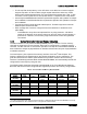

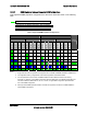
Table Of Contents
- 1. Introduction
- 2. Product Overview
- 3. Functional Architecture
- 3.1 Processor Support
- 3.1.1 Processor Population Rules
- 3.1.2 Multiple Processor Initialization
- 3.1.3 Enhanced Intel SpeedStep® Technology
- 3.1.4 Intel® Extended Memory 64 Technology (Intel® EM64T)
- 3.1.5 Execute Disable Bit Feature
- 3.1.6 Multi-Core Processor Support
- 3.1.7 Intel® Virtualization Technology
- 3.1.8 Platform Environmental Control Interface (PECI)
- 3.1.9 Common Enabling Kit (CEK) Design Support
- 3.2 Intel® 5400 Memory Controller Hub Chipset (Intel® 5400 MCH Chipset)
- 3.2.1 Processor Front-Side Buses
- 3.2.2 Snoop Filter
- 3.2.3 System Memory Controller and Memory Subsystem
- 3.2.3.1 Supported Memory
- 3.2.3.2 DIMM Population Rules and Supported DIMM Configurations
- 3.2.3.3 Minimum Memory Configuration
- 3.2.3.4 Memory upgrades
- 3.2.3.5 ECC Code Support
- 3.2.3.6 Memory Sparing
- 3.2.3.7 FBD Memory Thermal Management
- 3.2.3.8 BIOS Support of Memory Subsystem
- 3.2.3.9 Memory Error Handing
- 3.2.3.10 Memory Error Reporting
- 3.3 Intel® 6321ESB I/O Controller Hub
- 3.4 PCI Subsystem
- 3.4.1 Intel® 6321ESB I/O Controller Hub PCI32: 32-bit, 33-MHz PCI Bus Segment
- 3.4.2 Intel® 6321ESB I/O Controller Hub Port 1: x4 PCI Express* Bus Segment
- 3.4.3 Intel® 6321ESB I/O Controller Hub Port 2: x4 PCI Express* Bus Segment
- 3.4.4 MCH to Intel® 6321ESB I/O Controller Hub Chip-to-Chip Interface: Two x4 PCI Express* Bus Segments
- 3.4.5 MCH Ports 5-8: x16 Gen 2 PCI Express* Bus Segment
- 3.4.6 Scan Order
- 3.4.7 Resource Assignment
- 3.4.8 Automatic IRQ Assignment
- 3.4.9 Legacy Option ROM Support
- 3.4.10 EFI PCI APIs
- 3.4.11 Legacy PCI APIs
- 3.5 Video Support
- 3.6 Network Interface Controller (NIC)
- 3.7 Super I/O
- 3.1 Processor Support
- 4. Server Management
- 4.1 Intel® 6321ESB I/O Controller Hub Integrated Baseboard Management Controller (Integrated BMC) Feature Set
- 4.2 Advanced Configuration and Power Interface (ACPI)
- 4.3 System Initialization
- 4.4 Integrated Front Panel User Interface
- 4.5 Platform Control
- 4.6 Standard Fan Management
- 4.7 Private Management I2C Buses
- 4.8 Integrated BMC Messaging Interfaces
- 4.9 Event Filtering and Alerting
- 4.10 Watchdog Timer
- 4.11 System Event Log (SEL)
- 4.12 Sensor Data Record (SDR) Repository
- 4.13 Field Replaceable Unit (FRU) Inventory Device
- 4.14 Non-maskable Interrupt (NMI)
- 4.15 General Sensor Behavior
- 4.16 Processor Sensors
- 4.16.1 Processor Status Sensors
- 4.16.2 Processor VRD Over-temperature Sensor
- 4.16.3 ThermalTrip Monitoring
- 4.16.4 Internal Error (IERR) Monitoring
- 4.16.5 Dynamic Processor Voltage Monitoring
- 4.16.6 Processor Temperature Monitoring
- 4.16.7 Processor Thermal Control Monitoring (ProcHot)
- 4.16.8 CPU Population Error Sensor
- 4.17 Intel® Remote Management Module 2 (Intel RMM2) Support
- 5. System BIOS
- 5.1 BIOS Identification String
- 5.2 BIOS User Interface
- 5.2.1 Logo/Diagnostic Screen
- 5.2.2 BIOS Setup Utility
- 5.2.3 Server Platform Setup Utility Screens
- 5.2.3.1 Main Screen
- 5.2.3.2 Advanced Screen
- 5.2.3.3 Security Screen
- 5.2.3.4 Server Management Screen
- 5.2.3.5 Server Management System Information Screen
- 5.2.3.6 Boot Options Screen
- 5.2.3.7 Boot Manager Screen
- 5.2.3.8 Error Manager Screen
- 5.2.3.9 Exit Screen
- 5.3 Loading BIOS Defaults
- 5.4 Rolling BIOS
- 5.5 OEM Binary
- 6. Connector/Header Locations and Pin-outs
- 7. Jumper Block Settings
- 8. Intel® Light-Guided Diagnostics
- 9. Power and Environmental Specifications
- 9.1 Intel® Server Board S5400SF Design Specifications
- 9.2 Server Board Power Requirements
- 9.2.1 Processor Power Support
- 9.2.2 Power Supply DC Output Requirements
- 9.2.3 Power-on Loading
- 9.2.4 Grounding
- 9.2.5 Standby Outputs
- 9.2.6 Remote Sense
- 9.2.7 Voltage Regulation
- 9.2.8 Dynamic Loading
- 9.2.9 Capacitive Loading
- 9.2.10 Closed-Loop Stability
- 9.2.11 Common Mode Noise
- 9.2.12 Ripple/Noise
- 9.2.13 Soft Starting
- 9.2.14 Timing Requirements
- 9.2.15 Residual Voltage Immunity in Standby Mode
- 10. Regulatory and Certification Information
- Appendix A: Integration and Usage Tips
- Appendix B: POST Code Diagnostic LED Decoder
- Appendix C: POST Error Messages and Handling
- Appendix D: EFI Shell Commands
- Appendix E: Supported Intel® Server Chassis
- Appendix F: 1U PCI Express* Gen 2 Riser Card
- Glossary
- Reference Documents

Intel
®
Server Board S5400SF TPS Functional Architecture
Revision 2.02
Intel order number: D92944-007
15
3.1.2 Multiple Processor Initialization
IA-32 processors have a microcode-based bootstrap processor (BSP) arbitration protocol. The
BSP starts executing from the reset vector (F000:FFF0h). A processor that does not perform the
role of BSP is referred to as an application processor (AP).
The Intel
®
5400 Memory Controller Hub Chipset (Intel
®
5400 MCH Chipset) has two processor
front-side buses (FSB), each accommodating a single dual-core or quad-core Intel
®
Xeon
®
processor. At reset, the hardware arbitration chooses one BSP from the available processor
cores per FSB. However, the BIOS power-on self-test (POST) code requires only one processor
for execution. This requires the BIOS to elect a system BSP using registers in the Intel
®
5400
MCH Chipset. The BIOS cannot guarantee which processor will be the system BSP, only that a
system BSP will be selected. In the remainder of this document, the system BSP is referred to
as the BSP.
The BSP is responsible for executing the BIOS POST and preparing the server to boot the
operating system. At boot time, the server is in virtual wire mode and the BSP alone is
programmed to accept local interrupts (INTR) driven by the programmable interrupt controller
(PIC) and non-maskable interrupt (NMI)).
As part of the boot process, the BSP wakes each AP. When awakened, an AP programs its
memory type range registers (MTRRs) to be identical to those of the BSP. All APs execute a
halt instruction with their local interrupts disabled. If the BSP determines that an AP exists that
is a lower-featured processor or that has a lower value returned by the CPUID function, the BSP
switches to the lowest-featured processor in the server. The system management mode (SMM)
handler expects all processors to respond to an SMI.
3.1.3 Enhanced Intel SpeedStep
®
Technology
Enhanced Intel SpeedStep
®
Technology helps reduce average system power consumption and
potentially improves system acoustics by allowing the system to dynamically adjust processor
voltage and core frequency.
3.1.4 Intel
®
Extended Memory 64 Technology (Intel
®
EM64T)
Intel
®
Xeon
®
processors support Intel
®
Extended Memory 64 Technology (EM64T). Intel
®
64
architecture delivers 64-bit computing on server platforms when combined with supporting
software. Intel
®
64 architecture improves the performance by allowing systems to address more
than 4 gigabytes (GB) of both virtual and physical memory.
The following table identifies the three Intel
®
EM64T operating modes.
Table 4. Intel
®
EM64T Operating Modes
Legacy Mode Compatibility Mode 64-Bit Mode
32-bit operating system
32-bit applications
32-bit drivers
64-bit operating system
32-bit applications
64-bit drivers
4 GB address space
GPRs are 32-bit
64-bit operating system
64-bit applications
64-bit drivers
64-bit flat virtual address space
GPRs are 64-bit