
Technical Product Specification
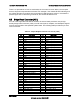
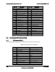


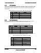

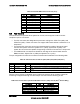
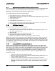
Table Of Contents
- 1. Introduction
- 2. Product Overview
- 3. Functional Architecture
- 3.1 Processor Support
- 3.1.1 Processor Population Rules
- 3.1.2 Multiple Processor Initialization
- 3.1.3 Enhanced Intel SpeedStep® Technology
- 3.1.4 Intel® Extended Memory 64 Technology (Intel® EM64T)
- 3.1.5 Execute Disable Bit Feature
- 3.1.6 Multi-Core Processor Support
- 3.1.7 Intel® Virtualization Technology
- 3.1.8 Platform Environmental Control Interface (PECI)
- 3.1.9 Common Enabling Kit (CEK) Design Support
- 3.2 Intel® 5400 Memory Controller Hub Chipset (Intel® 5400 MCH Chipset)
- 3.2.1 Processor Front-Side Buses
- 3.2.2 Snoop Filter
- 3.2.3 System Memory Controller and Memory Subsystem
- 3.2.3.1 Supported Memory
- 3.2.3.2 DIMM Population Rules and Supported DIMM Configurations
- 3.2.3.3 Minimum Memory Configuration
- 3.2.3.4 Memory upgrades
- 3.2.3.5 ECC Code Support
- 3.2.3.6 Memory Sparing
- 3.2.3.7 FBD Memory Thermal Management
- 3.2.3.8 BIOS Support of Memory Subsystem
- 3.2.3.9 Memory Error Handing
- 3.2.3.10 Memory Error Reporting
- 3.3 Intel® 6321ESB I/O Controller Hub
- 3.4 PCI Subsystem
- 3.4.1 Intel® 6321ESB I/O Controller Hub PCI32: 32-bit, 33-MHz PCI Bus Segment
- 3.4.2 Intel® 6321ESB I/O Controller Hub Port 1: x4 PCI Express* Bus Segment
- 3.4.3 Intel® 6321ESB I/O Controller Hub Port 2: x4 PCI Express* Bus Segment
- 3.4.4 MCH to Intel® 6321ESB I/O Controller Hub Chip-to-Chip Interface: Two x4 PCI Express* Bus Segments
- 3.4.5 MCH Ports 5-8: x16 Gen 2 PCI Express* Bus Segment
- 3.4.6 Scan Order
- 3.4.7 Resource Assignment
- 3.4.8 Automatic IRQ Assignment
- 3.4.9 Legacy Option ROM Support
- 3.4.10 EFI PCI APIs
- 3.4.11 Legacy PCI APIs
- 3.5 Video Support
- 3.6 Network Interface Controller (NIC)
- 3.7 Super I/O
- 3.1 Processor Support
- 4. Server Management
- 4.1 Intel® 6321ESB I/O Controller Hub Integrated Baseboard Management Controller (Integrated BMC) Feature Set
- 4.2 Advanced Configuration and Power Interface (ACPI)
- 4.3 System Initialization
- 4.4 Integrated Front Panel User Interface
- 4.5 Platform Control
- 4.6 Standard Fan Management
- 4.7 Private Management I2C Buses
- 4.8 Integrated BMC Messaging Interfaces
- 4.9 Event Filtering and Alerting
- 4.10 Watchdog Timer
- 4.11 System Event Log (SEL)
- 4.12 Sensor Data Record (SDR) Repository
- 4.13 Field Replaceable Unit (FRU) Inventory Device
- 4.14 Non-maskable Interrupt (NMI)
- 4.15 General Sensor Behavior
- 4.16 Processor Sensors
- 4.16.1 Processor Status Sensors
- 4.16.2 Processor VRD Over-temperature Sensor
- 4.16.3 ThermalTrip Monitoring
- 4.16.4 Internal Error (IERR) Monitoring
- 4.16.5 Dynamic Processor Voltage Monitoring
- 4.16.6 Processor Temperature Monitoring
- 4.16.7 Processor Thermal Control Monitoring (ProcHot)
- 4.16.8 CPU Population Error Sensor
- 4.17 Intel® Remote Management Module 2 (Intel RMM2) Support
- 5. System BIOS
- 5.1 BIOS Identification String
- 5.2 BIOS User Interface
- 5.2.1 Logo/Diagnostic Screen
- 5.2.2 BIOS Setup Utility
- 5.2.3 Server Platform Setup Utility Screens
- 5.2.3.1 Main Screen
- 5.2.3.2 Advanced Screen
- 5.2.3.3 Security Screen
- 5.2.3.4 Server Management Screen
- 5.2.3.5 Server Management System Information Screen
- 5.2.3.6 Boot Options Screen
- 5.2.3.7 Boot Manager Screen
- 5.2.3.8 Error Manager Screen
- 5.2.3.9 Exit Screen
- 5.3 Loading BIOS Defaults
- 5.4 Rolling BIOS
- 5.5 OEM Binary
- 6. Connector/Header Locations and Pin-outs
- 7. Jumper Block Settings
- 8. Intel® Light-Guided Diagnostics
- 9. Power and Environmental Specifications
- 9.1 Intel® Server Board S5400SF Design Specifications
- 9.2 Server Board Power Requirements
- 9.2.1 Processor Power Support
- 9.2.2 Power Supply DC Output Requirements
- 9.2.3 Power-on Loading
- 9.2.4 Grounding
- 9.2.5 Standby Outputs
- 9.2.6 Remote Sense
- 9.2.7 Voltage Regulation
- 9.2.8 Dynamic Loading
- 9.2.9 Capacitive Loading
- 9.2.10 Closed-Loop Stability
- 9.2.11 Common Mode Noise
- 9.2.12 Ripple/Noise
- 9.2.13 Soft Starting
- 9.2.14 Timing Requirements
- 9.2.15 Residual Voltage Immunity in Standby Mode
- 10. Regulatory and Certification Information
- Appendix A: Integration and Usage Tips
- Appendix B: POST Code Diagnostic LED Decoder
- Appendix C: POST Error Messages and Handling
- Appendix D: EFI Shell Commands
- Appendix E: Supported Intel® Server Chassis
- Appendix F: 1U PCI Express* Gen 2 Riser Card
- Glossary
- Reference Documents

Intel
®
Server Board S5400SF TPS Connector/Header Locations and Pin-outs
Revision 2.02
Intel order number: D92944-007
125
There is no precedence or lock-out mechanism for the control sources. When a new request
arrives, all previous requests are terminated. For example, if the chassis ID LED is blinking and
the chassis ID button is pressed, then the chassis ID LED changes to solid on. If the button is
pressed again with no intervening commands, the chassis ID LED turns off.
6.6 Bridge Board Connector (J4G1)
For use in the supported Intel
®
Server Chassis, the server board provides a 120-pin high-
density bridge board connector (J4G1) to route control panel, midplane, and backplane signals
from the server board to the specified system board. The following table provides the pin-outs
for this connector.
Table 67. 120-pin Bridgeboard Connector Pin-out (J4G1)
Pin Signal Name Pin Signal Name
A1 SMB_HOST_3V3_CLK B1 GND
A2 SMB_HOST_3V3_DAT B2 PE1_ESB_TXN_C<3>
A3 FM_BRIDGE_PRESENT_N B3 PE1_ESB_TXP_C<3>
A4 GND B4 GND
A5 PE1_ESB_RXN_C<3> B5 PE_WAKE_N
A6 PE1_ESB_RXP_C<3> B6 GND
A7 GND B7 PE1_ESB_TXN_C<2>
A8 FM_FAN_D_PRSNT6 B8 PE1_ESB_TXP_C<2>
A9 GND B9 GND
A10 PE1_ESB_RXN_C<2> B10 FM_FAN_D_PRSNT5
A11 PE1_ESB_RXP_C<2> B11 GND
A12 GND B12 PE1_ESB_TXN_C<1>
A13 FM_FAN_D_PRSNT4 B13 PE1_ESB_TXP_C<1>
A14 GND B14 GND
A15 PE1_ESB_RXN_C<1> B15 RST_MP_PWRGD
A16 PE1_ESB_RXP_C<1> B16 GND
A17 GND B17 PE1_ESB_TXN_C<0>
A18 FM_RAID_PRESENT B18 PE1_ESB_TXP_C<0>
A19 GND B19 GND
A20 PE1_ESB_RXN_C<0> B20 FM_RAID_MODE
A21 PE1_ESB_RXP_C<0> B21 GND
A22 GND B22 CLK_100M_SRLAKE_N
A23 FM_FAN_D_PRSNT1 B23 CLK_100M_SRLAKE_P
A24 FM_FAN_D_PRSNT3 B24 GND
A25 FM_FAN_D_PRSNT2 B25 SGPIO_DATAOUT1_R
A26 GND B26 SGPIO_DATAOUT0_R
A27 USB_ESB_P4P B27 SGPIO_LOAD_R
A28 USB_ESB_P4N B28 SGPIO_CLOCK_N
A29 GND B29 GND
A30 USB_ESB_OC_N<4> B30 USB_ESB_P2P
A31 USB_ESB_OC_N<3> B31 USB_ESB_P2N
A32 GND B32 GND
A33 USB_ESB_P3P B33 USB_ESB_OC_N<2>
A34 USB_ESB_P3N B34 NIC1_LINK_LED_N
A35 GND B35 NIC1_ACT_LED_N
A36 FP_NMI_BTN_N B36 LED_STATUS_GREEN_R1