
Technical Product Specification


Intel® Server System SR1560SF TPS Appendix D: Jumper Block Settings and Usage
Revision 1.2 71
Intel order number D92959-006
6. Power down and remove AC power.
7. Open the server and move the jumper from the “enabled” position (pins 2-3) to the
“disabled” position (pins 1-2).
8. Close the server system and reconnect AC power and power up the server.
Note: Normal BMC functionality is disabled with the force BMC update jumper set to the
“enabled” position. The server should never be run with the BMC force update jumper set in this
position and should only be used when the standard firmware update process fails. This jumper
should remain in the default – disabled position when the server is running normally.
BIOS Select Jumper
The jumper block at J3H1, located just to the left of the SSI control panel header, is used to
select which BIOS image the system will boot to. Pin 1 on the jumper is identified with a ‘▼’.
This jumper should only be moved if you wish to force the BIOS to boot to the secondary bank
which may hold a different version of BIOS.
The rolling BIOS feature of the baseboard will automatically alternate the Boot BIOS to the
secondary bank in the event the BIOS image in the primary bank is corrupted and cannot boot
for any reason.
AF002171
3
BIOS Select
1-2: Force
Lower Bank
2-3: Normal
Operation (Default)
3
J3H1
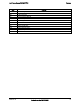
Pins What happens at system reset…
1-2 Force BIOS to bank 0
2-3 System is configured for normal operation (Default)
Note: When performing a BIOS update procedure, the BIOS select jumper must be set to its default
position (pins 2-3).
Figure 36. BIOS Select Jumper (J3H1)