
Technical Product Specification


Standard Control Panel Functionality Intel® Server System SR1560SF TPS
Revision 1.2
Intel order number D92959-006
50
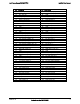
Color State Criticality Description
In mirrored configuration, when memory mirroring takes
place and system loses memory redundancy. This is not
covered by (2).
Redundancy loss such as power-supply or fan. This does
not apply to non-redundant sub-systems.
PCIe* link errors
CPU failure/disabled – if there are two processors and one
of them fails
Fan alarm – Fan failure. Number of operational fans should
be more than minimum number needed to cool the system
Non-critical threshold crossed – Temperature and voltage
Amber Blink Non-critical Non-fatal alarm – system is likely to fail
Critical voltage threshold crossed
VRD hot asserted
Minimum number of fans to cool the system not present or
failed
In non-sparing and non-mirroring mode if the threshold of
ten correctable errors is crossed within the window
Amber Solid on Critical, non-
recoverable
Fatal alarm – system has failed or shutdown
DIMM failure when there is one DIMM present, no good
memory present
Run-time memory uncorrectable error in non-redundant
mode
IERR signal asserted
Processor 1 missing
Temperature (CPU ThermTrip, memory TempHi, critical
threshold crossed)
No power good – power fault
Processor configuration error (for instance, processor
stepping mismatch)
7.2.2.1 System Status LED – BMC Initialization
When AC power is first applied to the system and 5V-STBY is present, the BMC controller on
the server board requires 15-20 seconds to initialize. During this time, the system status LED
will blink, alternating between amber and green, and the power button functionality of the control
panel is disabled, preventing the server from powering up. Once BMC initialization has
completed, the status LED will stop blinking and the power button functionality is restored and
can be used to turn on the server.
7.2.3 Drive Activity LED
The drive activity LED on the control panel indicates drive activity from the onboard hard disk
controllers.
7.2.4 System Identification LED
The blue system identification LED is used to help identify a system for servicing. This is
especially useful when the system is installed in a high density rack or cabinet that is populated
with several similar systems.