
Technical Product Specification


Standard Control Panel Functionality Intel® Server System SR1560SF TPS
Revision 1.2
Intel order number D92959-006
48
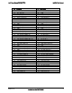
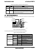
Table 38. Control Button and Intrusion Switch Functions
Reference Feature Function
A Power/Sleep
Button
Toggles the system power on/off. This button also functions as a Sleep
Button if enabled by an ACPI-compliant operating system.
B ID Button Toggles the front panel ID LED and the baseboard ID LED on/off. The
baseboard ID LED is visible through the rear of the chassis and allows you
to locate the server you’re working on from behind a rack of servers.
C Reset Button Reboots and initializes the system.
D NMI Button Pressing the recessed button with a paper clip or pin puts the server in a
halt state for diagnostic purposes and allows you to issue a non-maskable
interrupt. After issuing the interrupt, a memory download can be performed
to determine the cause of the problem.
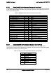
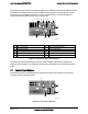
7.2 Control Panel LED Indicators
The control panel houses six LEDs, which are viewable with or without the front bezel to display
the system’s operating state.
AF002204
NIC1 and NIC2
Activity LEDs
Power and
Sleep LED
System
Identity LED
System
Status LED
Hard Drive
Activity LED
Figure 31. Control Panel LED Indicators
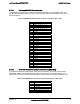
The following table identifies each LED and describes their functionality.
Table 39. Control Panel LED Functions
LED Color State Description
Green On NIC Link
NIC1/NIC2
Activity
Green Blink NIC Activity
On Legacy power on/ACPI S0 state Green
Blink
1,4
Sleep/ACPI S1 state
Power/Sleep
(on standby power)
Off Off Power Off/ACPI S4 or S5 state
Green/Ambe
r
Alternating
Blink
Pre DC Power On – 15-20 second
BMC Initialization
On Running/normal operation Green
Blink
1,2
Degraded
On Critical or non-recoverable condition. Amber
Blink
1,2
Non-critical condition.
System Status
(on standby power)
Off Off POST/system stop.
Disk Activity
Green Random blink Provides an indicator for disk activity.