
Technical Product Specification


Intel® Server System SR1560SF TPS Standard Control Panel Functionality
Revision 1.2
Intel order number D92959-006
47
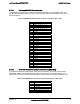
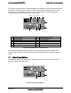
For systems configured with a hot-swap backplane, the standard control panel supports several
push buttons and status LEDs, along with USB and video ports to centralize system control,
monitoring, and accessibility to within a common compact design. The following diagram
overviews the layout and functions of the control panel.
AF002189
L JK
H
I
BA F GEDC
A NIC 2 Activity LED G System Identification LED
B NIC 1 Activity LED H System Identification Button
C Power/Sleep Button I System Reset Button
D Power/Sleep LED J USB 2.0 Connector
E Hard Drive Activity LED K Recessed NMI Button (Tool Required)
F System Status LED L Video Connector
Figure 29. Standard Control Panel Overview
The following sections described the features of the standard control panels. Differences
between control panels for the fixed hard drive and hot-swap hard drive configurations will be
noted.
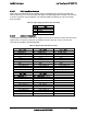
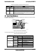
7.1 Control Panel Buttons
The standard control panel assembly houses several system control buttons. Each of their
functions is listed in the table below.
AF002203
D
B
C
A
Figure 30. Control Panel Buttons