
Technical Product Specification


Hard Disk Drive Support Intel® Server System SR1560SF TPS
Revision 1.2
Intel order number D92959-006
44
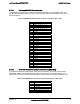
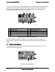
6.3.3.7 USB Floppy Drive Connector
With a slim-line USB floppy drive installed (using the optional floppy drive kit) into either the
slim-line drive bay or in one of the hard drive bays, the USB floppy cable is routed from the drive
to a 4-pin connector on the backplane. The following table provides the pin-out for the floppy
drive connector.
Table 34. 4-pin Floppy Connector Pin-out (J2B1)
Pin# Name
1 P5V_USB_P3
2 USBP3N
3 USBP3P
4 GROUND
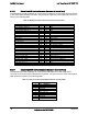
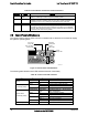
6.3.3.8 System Fan Connectors
The backplanes provides a pathway for signals from the server board to monitor and control five
system fans. A 1x10 mini connector is provided for each of the fans. The pin-out for each
connector is provided in the following table.
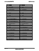
Table 35. System Fan Connector Pin-outs
J9A5 - FAN_1 J8A1- FAN_2 J7A1- FAN_3
PIN SIGNAL NAME PIN SIGNAL NAME PIN SIGNAL NAME
1 FAN_TACH5 1 FAN_TACH6 1 FAN_TACH7
2 FAN_PWM_CPU1 2 FAN_PWM_CPU1 2 FAN_PWM_CPU2
3 P12V 3 P12V 3 P12V
4 P12V 4 P12V 4 P12V
5 FAN_TACH1_H7 5 FAN_TACH2_H7 5 FAN_TACH3_H7
6 GND 6 GND 6 GND
7 GND 7 GND 7 GND
8 FAN_PRSNT1_N 8 FAN_PRSNT2_N 8 FAN_PRSNT3_N
9 LED_FAN1_FAULT 9 LED_FAN2_FAULT 9 LED_FAN3_FAULT
10 LED_FAN1 10 LED_FAN2 10 LED_FAN3
J6A1- FAN_4 J4B1- FAN_5
PIN SIGNAL NAME PIN SIGNAL NAME
1 FAN_TACH8 1 PCI_FAN_TACH10
2 FAN_PWM_CPU2 2 FAN_PWM3
3 P12V 3 P12V
4 P12V 4 P12V
5 FAN_TACH4_H7 5 FAN_TACH9
6 GND 6 GND
7 GND 7 GND
8 FAN_PRSNT4_N 8 FAN_PRSNT5_N
9 LED_FAN4_FAULT 9 LED_FAN5_FAULT
10 LED_FAN4 10 LED_FAN5