
Technical Product Specification


Hard Disk Drive Support Intel® Server System SR1560SF TPS
Revision 1.2
Intel order number D92959-006
42
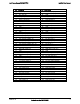
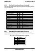
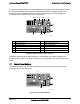
6.3.3.3 Control Panel I/O Interface Connector (Backplane to Control Panel)
The backplanes provide a pathway for control panel I/O signals from the bridge board connector
to the control panel interface connector. The pin-out for the 50-pin control panel I/O connector is
shown in the following table:
Table 30. Backplane Control Panel Connector Pin-out (J9C1)
Description Pin # Pin # Description
V_IO_RED_CONN_FP 1 2 GND
V_IO_GREEN_CONN_FP 3 4 GND
V_IO_BLUE_CONN_FP 5 6 GND
V_IO_HSYNC_BUFF_FP_L 7 8 GND
V_IO_VSYNC_BUFF_FP_L 9 10 GND
VIDEO_IN_USE 11 12 FP_THERM_SENSOR
EMP_DTR2_L 13 14 EMP_DCD2_L
EMP_RTS2_L 15 16 EMP_CTS2_L
EMP_SIN2_L 17 18 EMP_SOUT2
EMP_DSR2_L 19 20 EMP_IN_USE
FP_NMI_BTN_L 21 22 GND
NIC1_ACT_LED_L 23 24 NIC1_LINK_LED_R_L
25 26 FP_CHASSIS_INTRU
FP_ID_SW_L 27 28 SMB_PB1_5VSB_CLK
GND 29 30 SMB_PB1_5VSB_DAT
FP_RST_BTN_L 31 32 NIC2_ACT_LED_L
HDD_FAULT_LED_R_L 33 34 NIC2_LINK_LED_R_L
FP_PWR_BTN_L 35 36 FP_ID_LED_R_L
IPMB_I2C_5VSB_SCL 37 38 GND
IPMB_I2C_5VSB_SDA 39 40 HDD_LED_5V_A
FP_PWER_LED_R_N 41 42 FAULT_LED_5VSB_P
FP_PWR_LED_5VSB 43 44 LED_STATUS_AMBER_R1
RST_P6_PWRGOOD 45 46 LED_STATUS_GREEN_BUF_R1
HDD_LED_ACT_R_L 47 48 P5V
P5V_STBY 49 50 P5V_STBY
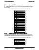
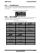
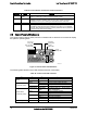
6.3.3.4 Control Panel USB Interface Connector (Backplane to Control Panel)
The backplanes provide a pathway for control panel USB signals from the bridge board
connector to the control panel USB interface connector. The pin-out for the 10-pin control panel
USB connector is shown in the following table.
Table 31. 1x10 Pin Control Panel USB Connector Pin-out (J6B1)
Pin# Description
1 P5V_USB_P1
2 USB_P1N
3 USB_P1P
4 GROUND
5 GROUND
6 P5V_USB_P2
7 USB_P2N
8 USB_P2P
9 GROUND
10 GROUND