
Technical Product Specification


Hard Disk Drive Support Intel® Server System SR1560SF TPS
Revision 1.2
Intel order number D92959-006
40
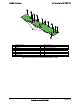
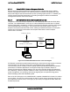
6.3.3.2 Bridge Board Interface (Backplane to Server Board)
The backplanes provide a pathway for the control panel, PCIe*, USB, and other miscellaneous
signals from the server board to connector interfaces on the backplane. The server board and
backplane have matching 120-pin connectors which are attached using a PCB called the Bridge
Board, as shown in the following figure. To assure the bridge board is held in place while the
integrated platform is shipped or installed into the rack, the bridge board is held in place using
metal clips which latch the bridge board to each of its connectors on the backplane and server
board.
AF002201
Figure 26. Bridge Board
The following table provides the pin-out for the 120-pin connector:
Table 29. Bridge Board Connector Pin-out (J5A1)
PIin SIignal Name PIin SignalL Name
1 GND 61 SMB_SENSOR_3V3SB_CLK_BUF
2 PE1_ESB_TX_DN3 62 SMB_SENSOR_3V3SB_DAT_BUF
3 PE1_ESB_TX_DP3 63 FM_BRIDGE_PRSNT_N
4 GND 64 GND
5 PE_WAKE_N 65 PE1_ESB_RX_DN_C3
6 GND 66 PE1_ESB_RX_DP_C3
7 PE1_ESB_TX_DN2 67 GND
8 PE1_ESB_TX_DP2 68 FAN_PRSNT6_N
9 GND 69 GND
10 FAN_PRSNT5_N 70 PE1_ESB_RX_DN_C2
11 GND 71 PE1_ESB_RX_DP_C2
12 PE1_ESB_TX_DN1 72 GND
13 PE1_ESB_TX_DP1 73 FAN_PRSNT4_N
14 GND 74 GND
15 RST_PS_PWRGD 75 PE1_ESB_RX_DN_C1
16 GND 76 PE1_ESB_RX_DP_C1
17 PE1_ESB_TX_DN0 77 GND
18 PE1_ESB_TX_DP0 78 RAID_KEY_PRES
19 GND 79 GND