
Technical Product Specification


Intel® Server System SR1560SF TPS Hard Disk Drive Support
Revision 1.2
Intel order number D92959-006
39
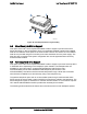
6.3.2 LED Support
The backplanes support an activity/fault LED for each of the hard drive connectors. The LED will
illuminate green for activity or amber for a drive fault. The green activity LED is driven by the
SAS/SATA hard disk drive directly. The amber fault LED is driven by the VSC410* management
controller whenever a fault condition is detected. When the drive is used in a RAID
configuration, the RAID controller will have control over the fault LED and it may exhibit different
behavior.
Table 26. LED Function
Status LED Definition
Green HDD Activity
Amber HDD Fail
The activity LED functionality is controlled directly by the hard drives. This causes the LED to
function differently between SAS and SATA drives. The expected operation is outlined below.
Table 27. Hard Drive Activity LED Functionality
Condition Drive Type Behavior
SAS Ready LED stays on Power on with no drive activity
SATA Ready LED stays off
SAS Ready LED blinks off when processing a command Power on with drive activity
SATA Ready LED blinks on when processing a command
SAS Ready LED stays off Power on and drive spun down
SATA Ready LED stays off
SAS Ready LED blinks Power on and drive spinning up
SATA Ready LED stays off
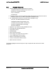
6.3.3 Backplane Connector Definitions
The backplanes include several different connectors. This section defines the purpose and pin-
out associated with each.
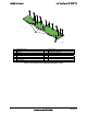
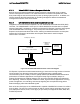
6.3.3.1 Power Connector (Backplane to Power Supply Harness)
The backplane provides power to the three hard drive bays and the slim-line drive bay. An 8-pin
power cable is routed from the power supply and plugs into a 2x4 shrouded plastic PC power
connector on the backplane. The following table shows the power connector pin-out.
Table 28. Backplane Power Connector Pin-out (J1B1)
Pin Name Pin Name
1 Ground 5 +12V
2 Ground 6 +12V
3 +5V 7 5VSB
4 +5V 8 +3.3V