
Technical Product Specification


Cooling Sub-System Intel® Server System SR1560SF TPS
Revision 1.2
Intel order number D92959-006
26
Pin Definition Pin # Pin Definition
PCI_FAN_TACH9 23 24 CONN_PIN24_R
PCI_FAN_TACH10 25 26 FM_SIO_TEMP_SENSOR
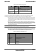
The system fan board includes a 2x4 power connector which is connected with the P3 power
harness of the power supply. The connector has the following pin-out
Table 23. System Fan Board Power Connector (J3B1) Pin-out
Pin Definition Pin# Pin Definition
+12V 5 1 Ground
+12V 6 2 Ground
+5V Standby 7 3 +5V
+3.3V 8 4 +5V
4.2 Power Supply Fans
The power supply supports two non-redundant 40mm fans. They are responsible for the cooling
of the power supply, first hard drive bay, and slim-line drive bay. These fans are not
replaceable. Should a power supply fan fail, the entire power supply must be replaced.
4.3 CPU Air Duct and Air Baffle
The chassis requires the use of a CPU air duct and power supply/electronics bay isolation air
baffle to direct airflow over critical areas within the system.
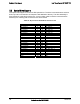
An air baffle is used to isolate airflow of the two power supply fans from that of the system fan
assembly. The baffle is mounted into three stand-offs with one end fitting under the back edge
of the hard drive bay.
AF002194
Figure 14. Air Baffle
The CPU air duct must be properly installed to direct airflow through the processor heatsink(s)
to the memory area of the system. The CPU air duct is designed to support either a single or
dual processor configuration. For single processor configurations, the fabricated air dam must
be left in place to prevent air from by-passing the installed processor. If the air dam is removed
with only one processor installed, the system will not meet the cooling requirements of the
processor, which will most likely result in a thermal shutdown of the system.