
Technical Product Specification


Cooling Sub-System Intel® Server System SR1560SF TPS
Revision 1.2
Intel order number D92959-006
24
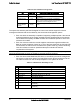
Table 20. Non-redundant Cooling Zones
Fan Cooling Zone Description of greatest cooling influence
System Fan #1/2 CPU1 Primary cooling for CPU1 and memory
System Fan #3/4 CPU2 Primary cooling for hard drive2, CPU2, the MCH,
and memory
System Fan #5 PCI Primary cooling for hard drive1, PCI Express*
add-in cards, and server board components that
components in the full height PCI zone
Power Supply
Fans 2 fans per
module
Power
Supply
Primary cooling for hard drive 0, and the power
supply
The system fan assembly has been designed for ease of use and has support for several
management features that can be utilized by the server board management system.
Each fan within the assembly is capable of supporting multiple speeds. If the internal
ambient temperature of the system exceeds the value programmed into the thermal
sensor data record (SDR), the BMC firmware will increase the speed for all the fans
within the fan module.
Each fan connector within the module supplies a tachometer signal that allows the
BMC to monitor the status of each fan. If one of the fans should fail, the fan fault LED
will illuminate, the failure will be recorded to the system event log, and the remaining
fans will increase to maximum speed and attempt to maintain the thermal
requirements of the system.
Note: This system does not have support for redundant cooling. If a fan should fail, the system
should be brought down as soon as possible to have the faulty fan replaced.
Each fan has an associated fault LED which is controlled by the server management
sub-system on the server board. The fault LEDs for each fan are located next to the
fan cable connectors on the hot-swap backplane or the system fan board.
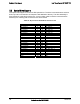
Table 21. Individual Fan Assembly Pin-out
Pin Signal Name Description
1 Fan Tach b Tachometer signal from 1
st
fan rotor
2 PWM PWM control signal
3 +12V Power Supply 12V
4 +12V Power Supply 12V
5 Fan Tach a Tachometer signal from 2
nd
fan rotor
6 Ground Power Supply Ground
7 Ground Power Supply Ground
8 Not used Not used
9 Loopback wire Loopback to pin 10 to enable backplane presence LED
functionality
10 Loopback wire Loopback to pin 9 to enable backplane presence LED
functionality