
Technical Product Specification


Intel® Server System SR1560SF TPS Power Sub-System
Revision 1.2
Intel order number D92959-006
15
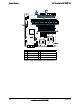
3.2 Output Connectors
The power supply has a cable harness with four power connectors used to power various
platform sub-systems. The following table defines each power connector
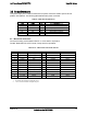
Table 5. Cable Harness Definition
From Length To Description
Case 230 P1 Main Power Connector
Case 270 P2 Processor Power Connector
Case 387 P3 Backplane power Connector
Case 260 P4 Power Signal Connector
P3 165 P5 SATA Power Connector
P5 165 P6 SATA Power Connector
P1 – Main Power Connector
Connector housing: 24-Pin Molex* Mini-Fit Jr. 39-01-2245 or equivalent
Contact: Molex Mini-Fit, HCS, Female, Crimp 44476 or equivalent
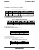
Table 6. P1 – Main Power Connector Pin-out
Pin Signal 18 AWG Color Pin Signal 18 AWG Color
1 +3.3 VDC Orange 13 +3.3 VDC Orange
2 +3.3 VDC Orange 14 -12 VDC Blue
3 COM Black 15 COM Black
4 +5 VDC* Red 16 PSON# Green
5 COM Black 17 COM Black
6 +5 VDC Red 18 COM Black
7 COM Black 19 COM Black
8 PWR OK Gray 20
Reserved
N.C.
9 5VSB Purple 21 +5 VDC Red
10 +12V3 Yellow/Blue Stripe 22 +5 VDC Red
11 +12V3 Yellow/Blue Stripe 23 +5 VDC Red
12 +3.3 VDC Orange 24 COM Black
Notes:
1. 5V Remote Sense Double Crimped into pin 4.
2. 3.3V Locate Sense Double Crimped into pin 2.