
Technical Product Specification


Product Overview Intel® Server System SR1560SF TPS
Revision 1.2
Intel order number D92959-006
10
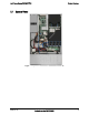
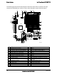
The following figure shows the board layout of the server board. Each connector and major
component is identified by a number or letter, and a description is given below the figure:
K
L
J
I
H
GFEDCBA
MN
O
QS
P
R
T
U
V
W
X
Y
Z
AA
BB
CC
DD
EE
FF
GG
HH
II
JJ
KK
LL
MM
NN
OO
AF002390
A Intel
®
RMM2 NIC Connector U Main Power Connector
B IO Module Option Connector V Battery
C POST Code Diagnostic LEDs W Power Supply Management Connector
D PCI Express* Riser Connector (x16 Gen2) X Dual Port USB 2.0 Header (USB0-1)
E System Identification LED - Blue Y SATA0
F System Status LED – Green/Amber Z SATA1
G External IO Connectors AA SATA2
H FBDIMM Memory Sockets BB SATA3
I Serial ‘B’ Port Configuration Jumper CC SATA4
J Processor 1 Socket DD SATA5
K Processor 2 Socket EE SATA SW RAID 5 Activation Key Connector
L Processor 1 Fan FF Intel
®
Remote Management Module 2
Connector
M Bridge Board Connector GG BMC FRU Update Jumper
N SSI 24-pin Control Panel Header HH CMOS Clear Jumper
O Processor 2 Fan II Password Clear Jumper
P Fan Board Connector JJ Chassis Intrusion Switch Header
Q System Fan 2 KK 3-pin IPMB Header
R CPU Power Connector LL 4-pin IPMB Header