
User guide


xv
List of Figures
Figure 1. Intel
®
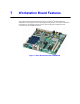
Workstation Board S5000XVN......................................................................... 1
Figure 2. Connector and Component Locations........................................................................ 4
Figure 3. Configuration Jumpers............................................................................................... 7
Figure 4. Back Panel Connectors and LEDs........................................................................... 11
Figure 5. DIMM Sockets.......................................................................................................... 16
Figure 6. BIOS Bank Select Jumper in Force Lower Bank Position........................................ 23
Figure 7. Password Clear Jumper in Clear Password Position............................................... 24
Figure 8. CMOS Clear Jumper in the Clear CMOS Position................................................... 25
Figure 9. Locating DIMM Sockets ........................................................................................... 28
Figure 10. Installing FBDIMMs................................................................................................ 29
Figure 11. Locating Processor Sockets................................................................................... 31
Figure 12. Opening Processor Socket Lever .......................................................................... 32
Figure 13. Opening Load Plate ............................................................................................... 32
Figure 14. Removing Protective Cover from Load Plate......................................................... 33
Figure 15. Setting Processor in Place..................................................................................... 33
Figure 16. Installing Heatsink (passive heatsink shown)......................................................... 35
Figure 17. Locating Active Heatsink Cable Connections ........................................................ 36
Figure 18. Opening Processor Socket Lever .......................................................................... 38
Figure 19. Opening Load Plate ............................................................................................... 38
Figure 20. Removing Processor from Socket.......................................................................... 39
Figure 21. Installing Protective Cover onto Load Plate ........................................................... 39
Figure 22. Locating and Removing the CMOS Battery ........................................................... 41