
Technical Product Specification


Functional Architecture Intel® Server Boards S5000PSL and S5000XSL TPS
Revision 1.7
Intel order number: D41763-008
26
3.2.1.3 PE0: One x4 PCI Express* Bus Segment
One x4 PCI Express* bus segment is directed through the ESB2-E. This PCI Express* segment,
PE0, is routed to PCI Express* Slot 4 that is special keyed to support ROMB card.
3.2.1.4 PE1: One x4 PCI Express* Bus Segment
One x4 PCI Express* bus segment is directed through the ESB2-E. This PCI Express* segment,
PE1, is routed to PCI Express* Slot 3. This becomes a x8 PCI Express* bus segment by
combining PE2 with PE1 for SATA server board or ROMB server board that do not have on-
board SAS controller.
3.2.1.5 PE2: One x4 PCI Express* Bus Segment
One x4 PCI Express* bus segment is directed through the ESB2-E. This PCI Express* segment,
PE2, is routed to PCI Express* Slot 3 for server boards that do not have on-board SAS
controller (SATA server board or ROMB server board), or to the on-board SAS controller for
server boards that do have on-board SAS controller (SAS server board).
3.2.1.6 PE4, PE5: Two x4 PCI Express* Bus Segments
Two x4 PCI Express* bus segments are directed through the MCH. These PCI Express*
segments, PE4 and PE5, are routed to PCI Express* Slot 5.
3.2.1.7 PE6, PE7: Two x4 PCI Express* Bus Segments
Two x4 PCI Express* bus segments are directed through the MCH. These PCI Express*
segments, PE6 and PE7, are routed to PCI Express* Slot 6.
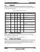
3.2.1.8 PCI Express* Riser Slot
PCI Express* Slot 6 supports third-party riser cards for both 1U and 2U system configurations.
Two PCI Express* pins are designated as Riser Type pins with the definitions noted in the
following table: