
Technical Product Specification


Jumper Blocks Intel® Server Boards S5000PSL and S5000XSL TPS
Revision 1.7
Intel order number: D41763-008
50
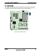
6.2 BMC Force Update Procedure
When performing a standard BMC firmware update procedure, the update utility places the
BMC into an update mode, allowing the firmware to load safely onto the flash device. In the
unlikely event that the BMC firmware update process fails due to the BMC not being in the
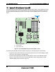
proper update state, the server board provides a BMC Force Update jumper (J1E3), which will
force the BMC into the proper update state. The following procedure should be followed in the
event the standard BMC firmware update process fails.
1. Power down and remove the AC power cord.
2. Open the server chassis. See your server chassis documentation for instructions.
3. Move jumper from the default operating position, covering pins1 and 2, to the enabled
position, covering pins 2 and 3.
4. Close the server chassis.
5. Reconnect the AC cord and power up the server.
6. Perform the BMC firmware update procedure as documented in the README.TXT file
that is included in the given BMC firmware update package. After successful completion
of the firmware update process, the firmware update utility may generate an error stating
that the BMC is still in update mode.
7. Power down and remove the AC power cord.
8. Open the server chassis.
9. Move jumper from the enabled position, covering pins 2 and 3 to the disabled position,
covering pins 1 and 2.
10. Close the server chassis.
11. Reconnect the AC cord and power up the server.
Note: Normal BMC functionality is disabled with the Force BMC Update jumper set to the
enabled position. The server should never be run with the BMC Force Update jumper set in this
position. This jumper setting should only be used when the standard firmware update process
fails. This jumper should remain in the default/disabled position when the server is running
normally.
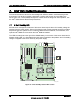
6.3 BIOS Select Jumper
The jumper block at J1C3, located at the left of PCI-X slot 1, is used to select the BIOS image to
which the system will boot. Pin 1 on the jumper is identified with a ‘▼’. This jumper should only
be moved if you want to force the BIOS to boot to the secondary bank, which may hold a
different version of BIOS.
The BIOS update is supported when the Recovery jumper is set on either pins 1-2 (recovery
mode), or pins 2-3 connected (normal mode).