
Technical Product Specification


Intel® Server Boards S5000PSL and S5000XSL TPS Functional Architecture
Revision 1.7
Intel order number: D41763-008
21
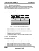
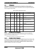
Table 7. Supported DIMM Configurations
Branch 0
Branch 1
Channel A Channel B
Channel C Channel D
DIMM_A
1
DIMM_A
2
DIMM_B
1
DIMM B2 DIMM C1 DIMM C2 DIMM D1 DIMM D2
Mirroring
Possible
Sparing
Possible
Y (0)
Y
Y (0)
Y Y (0, 1)
Notes:
Single channel mode is only tested and supported with a 512MB x8 FBDIMM installed in DIMM Slot A1.
The supported memory configurations must meet population rules defined above.
For best performance, the number of DIMMs installed should be balanced across both memory
branches. For example: a four-DIMM configuration will perform better than a two-DIMM configuration
and should be installed in DIMM slots A1, B1, C1, and D1. An eight-DIMM configuration will perform
better then a six-DIMM configuration.
Although mixed DIMM capacities between channels are supported, Intel does not validate DIMMs in mixed
DIMM configurations.
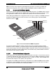
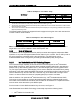
3.1.3.3.1 Minimum Non-Mirrored Mode Configuration
The server board is capable of supporting a minimum of one DIMM installed. However, for
system performance reasons, Intel’s recommendation is that at least two DIMMs be installed.
The following diagram shows the recommended minimum DIMM memory configuration.
Populated DIMM slots are shown in gray.
TP02300
DIMM D2
DIMM D1
DIMM C2
DIMM C1
DIMM B2
DIMM B1
DIMM A2
DIMM A1
Branch 0
MCH
Channel A
Channel B
Channel D
Channel C
Branch 1
Figure 13. Minimum Two DIMM Memory Configuration