
Technical Product Specification


Intel® Remote Management Module IntelP®P Remote Management Module Environmental/Electrical Specifications
4.2 Environmental
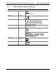
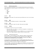
The table below details required environmental specifications.
Table 5. Environmental Specifications
Specifications
Relative Humidity
10% to 90% non-condensing
Elevation
3050 meters
DC Input Voltage
± 5% of all Nominal voltages
Shock (unpackaged)
Trapezoidal, 50g, 170 inches/sec
Shock (packaged)
36 inches
Vibration (unpackag
random
ed)
5 Hz to 500Hz 3.13g RMS
4.3 3.3 V Auxiliary Operation
The Intel
®
Remote Management Module operates on 3.3 V auxiliary power. The 3.3 V auxiliary
rail is a low power supply provided by the baseboard. It is active whenever the system is
plugged into AC power.
The baseboard generates the 3.3 V auxiliary supply from the system’s 5 V Standby power rail
when the system is off. Certain other devices on the server baseboard also operate on 5V
standby power to provide complete management functionality. When system power is on, the
baseboard generates this power from the 3.3 V system power rail.
The Intel
®
RMM can only be attached and removed when the AC power is disconnected from
the server.
4.4 Power System
The Intel
®
RMM is powered from the system’s standby power rail. The Intel
®
RMM implements
its own power-on reset control. The duration of this reset is sufficient to allow all clocks and PLL
circuits to stabilize before the Intel
®
RMM is taken out of reset.
There is also a one-second delay from the time the Intel
®
RMM is taken out of reset to the first
attempt to communicate with the baseboard. This delay is to allow the baseboard to come out of
its own power-on reset.
The cold reset signal for the Intel
®
RMM is called AC present.
Revision 1.0
25