
Technical Product Specification


Intel® RAID Smart Battery AXXRSBBU3 Technical Product Specification Hardware
Revision 1.6
Intel order number D84273-006
8
Broadcasts event alarms to the host:
- Out-of-temperature
- Terminate charge
- Terminate discharge
- Low capacity
Displays manufacturing information
Provides Smart Charger Protocol for improved battery maintenance, calibration, and
charging performance
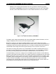
2.6 Connector Cable
A 5-pin connector cable connects the battery pack to the Intel
®
RAID Smart Battery
AXXRSBBU3 circuit board.
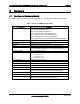
Table 4. Connector Pin-outs
Pin Signal Name I/O Description
1 VBATP Input Battery positive terminal
2 THERMISTOR SENSE Output Sense contact of the thermistor
3 GND Input Battery negative terminal
4 SCL Output I
2
C Clock for pack monitoring
5 SDA Input I
2
C Data for pack monitoring
2.7 Battery Pack
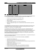
The cache-memory hold time depends on the size and configuration of the RAID
controller/module memory. Retention time varies depending on memory capacity and the
number of memory components used on the DIMM to support that capacity. Estimates for
battery backup retention time with different configurations of DDR2 memory are listed:
256 MB (256 Mb devices) = 46 hours
512 MB (256 Mb devices) = 23 hours
512 MB (512 Mb devices) = 46 hours
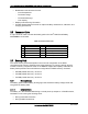
2.7.1 Battery States
The battery pack includes battery sensing logic that senses the battery voltage levels and
recognizes the battery state.
2.7.1.1 Initialized State
The battery is in the initialized state during a normal power-up sequence. In RAID firmware,
initialization occurs during the following times:
During boot loader execution
During RAID firmware boot