
Technical Product Specification


Connector/Header Locations and Pin-outs Intel® Server Boards S5000PSL and S5000XSL TPS
Revision 1.7
Intel order number: D41763-008
46
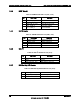
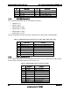
Table 35. External USB Connector Pin-out (JA6A1, JA6A2)
Pin Signal Name Description
1 USB_OC USB_PWR
2 USB_PN DATAL0 (Differential data line paired with DATAH0)
3 USB_PP DATAH0 (Differential data line paired with DATAL0)
4 GND Ground
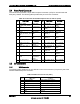
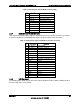
One 2x5 connector on the server board (J3J1) provides an option to support additional two USB
ports. The pin-out of the connector is detailed in the following table:
Table 36. Internal USB Connector Pin-out (J3J1)
Pin Signal Name Description
1 USB2_VBUS5 USB power (port 5)
2 USB2_VBUS4 USB power (port 4)
3 USB_ESB_P5N_CONN USB port 5 negative signal
4 USB_ESB_P4N_CONN USB port 4 negative signal
5 USB_ESB_P5P_CONN USB port 5 positive signal
6 USB_ESB_P4P_CONN USB port 4 positive signal
7 Ground
8 Ground
9 Key No pin
10 TP_USB_ESB_NC Test point
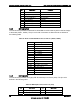
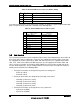
5.6 Fan Headers
The server board provides four SSI-compliant 4-pin and four SSI-compliant 6-pin fan headers to
be used as CPU, and I/O cooling fans. 3-pin fans are supported on all fan headers. 6-pin fans
are supported on headers J3H4, J3H3, J3H2, and J3H1. 4-pin fans are supported on headers
J9J1, J5J1, J3H4, J3H3, J9B4, and J9B3. 4-pin fans are not supported on header J3H2, and
J3H1, since these headers are tied to the CPU1 PWM. These fan headers should also not be
used for CPU cooling fans. The pin configuration for each of the 4-pin and 6-pin fan headers is
identical and is defined in the following tables.
Two 4-pin fan headers are designated as processor cooling fans:
- CPU1 fan (J9J1)
- CPU2 fan (J5J1)
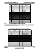
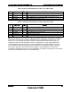
Four 6-pin fan headers are designated as hot-swap system fans:
- Hot-swap system fan 1 (J3H4)
- Hot-swap system fan 2 (J3H3)
- Hot-swap system fan 3 (J3H2)
- Hot-swap system fan 4 (J3H1)
Two 4-pin fan headers are designated as rear system fans:
- System fan 5 (J9B4)
- System fan 6 (J9B3)