
Technical Product Specification

Intel® Server Boards S5000PSL and S5000XSL TPS Connector/Header Locations and Pin-outs
Revision 1.7
Intel order number: D41763-008
37
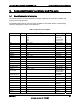
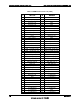
Table 16. 12 V Power Connector Pin-out (J3J2)
Pin Signal Color
1 GND Black
2 GND Black
3 GND Black
4 GND Black
5 +12 Vdc Yellow/black
6 +12 Vdc Yellow/black
7 +12 Vdc Yellow/black
8 +12 Vdc Yellow/black
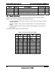
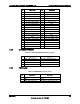
Table 17. Power Supply Signal Connector Pin-out (J9D1)
Pin Signal Color
1 SMB_CLK_ESB_FP_PWR_R Orange
2 SMB_DAT_ESB_FP_PWR_R Black
3 SMB_ALRT_3_ESB_R Red
4 3.3 V SENSE- Yellow
5 3.3 V SENSE+ Green
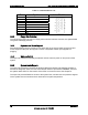
Table 18. P12V4 Power Connector Pin-out (J5A2)
Pin Signal Color
1 GND Black
2 GND Black
3 +12 Vdc Yellow/black
4 +12 Vdc Yellow/black
5.3 System Management Headers
5.3.1 Intel
®
Remote Management Module (Intel
®
RMM) Connector
A 120-pin Intel
®
RMM connector (J5B1) is included on the server board to support the optional
Intel
®
Remote Management Module. There is no support for third-party ASMI cards on this
server board.
Note: This connector is not compatible with the Intel
®
Server Management Module Professional
Edition (Product Code: AXXIMMPRO) or the Intel
®
Server Management Module Advanced
Edition (Product Code: AXXIMMADV).