
Technical Product Specification
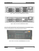

Physical and Electrical Description Intel® Local Control Panel TPS
Revision 1.2
Intel order number C96442-003
10
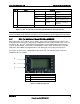
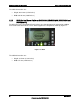
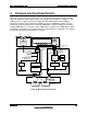
2.4.1 Controller Board Function
The LCD controller board includes the Silicon Labs* 8051F023 microcontroller, 5 V standby-to-
3.3 V standby converter, an LCD module, and LCD navigation buttons. The 8051F023
microcontroller in the control panel uses a 512 KB flash memory component. This supports the
base functional code and the roman font character sets.
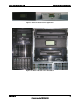
2.4.2 Connectors
2.4.2.1 External Connectors
SKU1 of the Intel
®
Local Control Panel has two USB connectors. SKU2 and SKU3 do not have
USB connectors.
2.4.2.2 Internal Connectors
SKU1 has four internal connectors:
A 50-pin header provides control and status information to and from the server board
through the backplane board. A 50-pin flat cable connects the front panel to the
backplane board. The backplane provides a signal path to a 100-pin connector, which is
cabled to the server board.
A 10-pin header provides the pathway for USB ports from the server board to the front of
the chassis. A 10-pin cable connects the Intel
®
Local Control Panel USB ports to the
server board.
A 4-pin jumper harness connects the NMI switch and LM30 temp sensor on the Intel
®
Local Control Panel I/O connector board to the Intel
®
Local Control Panel control board.
A 4-pin header provides control and status information to/from the server board via the
IPMB interface. A 4-pin round cable connects the Intel
®
Local Control Panel to the server
board.
SKU2 has one internal connector:
A 50-pin header provides control and status information to and from the server board
through the front panel board. A 50-pin flat cable connects the front panel to the
backplane board in the Intel
®
Server Platform SR6850HW4 (M) and to the front panel in
the Server Platform SR4850HW4 (M). The backplane provides a signal path to the Intel
®
Server Board SE8500HW4 or SE8501HW4.
SKU3 has one internal connector:
A 4-pin header provides control and status information to/from the server board via the
IPMB interface. A 4-pin round cable connects the Intel
®
Local Control Panel to the server
board.
See Appendix A for the different connectors and pin-outs.