
Technical Product Specification

IntelP®P Remote Management Module Environmental/Electrical Specifications Intel® Remote Management Module
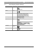
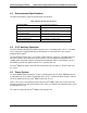
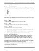
The table below summarizes the DC specifications of the bus, which applies for both master
e:
and slav
Table 9. FML Bus DC Specifications
Limits Symbol Parameter
Minimum Maximum
Units Comments
Vil Data, Clock input low voltage - 0.8 V
Vih Data, Clock input high voltage 2.0 - V
Vol Data, clock output low voltage - 0.4 V
Voh Data, clock output high voltage 2.4 - V
Vdd Nominal bus voltage 3.0 3.6 V 3.3V typical
Iih Input high current - 15 uA
Iil Input low current 15 - uA
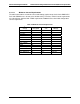
4.4.3.2 IPMB Specifications
uses 3.3 V signaling.
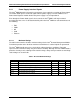
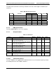
4.4.3.3 AC Specifications
The Intel
®
RMM IPMB bus
Table 10. I
2
C Interface
Symbol Parameter Minimum Maximum Unit Notes
Freq Operating frequency 400 KHz
Tbuf Bus free time between Stop and Start condition 4
(= Tcyc * (I2C_CLK_DIV+16))
.7 us
thd:sta
Hold time after (repeated) start condition. After this
period, the first clock is generated
4.0 us
(= Tcyc * (I2C_CLK_DIV-8))
tsu:sta
(= Tcyc * (I2C_CLK_DIV+15))
Repeated Start condition setup time 4.0 us
tsu:sto Stop condition setup time
(=
4.0 us
Tcyc * (I2C_CLK_DIV+15))
thd:data Data hold time from SCL 300 ns
tsu:data Data setup time to SCL 250 ns
Tf Clock/Data fall time into 100 pF capacitance and
4.7K ohm pullup.
300 ns 1
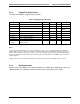
4.4.3.3.1 16550 UART Interface
The Intel
®
RMM has one 16550 UART* (RS232) interface for serial communication. By default,
the RS232 port on the Intel
®
RMM is disabled.
Revision 1.0
30