
Technical Product Specification
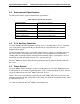

Intel® Remote Management Module IntelP®P Remote Management Module Environmental/Electrical Specifications
4.4.3.1 FML Bus Specifications
rd communication bus for management
traffic. It can handle all network traffic types and Internet protocols. The FML bus is comprised
of four signals:
MCL
INTEX
DA
DA
4 M
MCL is the FML Clock output. This signal is driven by the FML master. In this case, the master
is the BMC.
4 M
he MDA signal is the FML Data Out signal. It is driven by the BMC.
3 SDA
e has two uses. The uses are as follows:
states in the active transaction).
During times when the FML bus is idle, the SINTEX line acts as an attention interrupt
tiate an FML bus Read transaction.
4.4.3.1.4.1 FML Bus Read Transaction
When the BMC sees the interrupt line asserted, it will initiate a FML bus Read transaction.
During this transaction, the Intel
®
RMM will send a command header to the BMC that is
appropriate to the task being initiated. If the Intel
®
RMM is sending data to the BMC, the
transaction will be a FML Write transaction, including data.
If the transaction is a multi-command sequence, the BMC will initiate further FML Read
transactions to receive the command sequence. This is completed using one or more “Middle”
and one “End” command transactions to complete the packet transfer.
If the Intel
®
RMM is receiving data from the BMC, the Intel
®
RMM will send a command header
showing its available buffer space. Then the BMC will end the transaction and initiate a new
transaction to carry out the data transfer.
The Fast Management Link (FML) is an Intel standa
S
M
S
.4.3.1.1 CL
.4.3.1.2 DA
T
4.4.3.1.
The SDA is the FML Data In signal. This signal is driven by the Intel
®
RMM.
4.4.3.1.4 SINTEX
The SINTEX lin
During transactions on the FML, it is used for cycle elongation (i.e. to introduce wait
from the Intel
®
RMM to the BMC, to ini
Revision 1.0
29