
Technical Product Specification

IntelP®P Remote Management Module Environmental/Electrical Specifications Intel® Remote Management Module
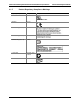
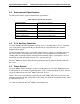
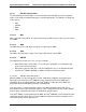
4.4.2 Supply Rail Specifications
The table below outlines supply rail specifications:
Table 8. Supply Rail Specifications
Symbol Parameter Minimum Maximum Unit Comments
Vcc 3.3 V main pow V er rail 3.13 3.45
Vcc rise 3.3 V main rise time 5 70 mS 10% to 90%
Vcc Aux 3.3V wer On 3.13 3.45 Vcc present or
absent
Aux Rail, Po or Off V
Vcc Aux rise 3.3V Aux rise time 1 25 mS 10% to 90%
Icc inrush Peak current 1.5 A <1.5mS
Icc Aux inrush P 1.5 A <1.5 mS eak current
Vcc Cap DC decoupling capacitance 100 uF
Vcc Aux Cap DC decoupling capacitance 140 uF
Icc Aux
Leakage
Cross voltage leakage current (Vcc
a
1 mA Vcc is off
uxiliary to VCC)
Notes:
Inrush is measured from the time the 3.3 V rail is from 0.4 V to 3.13 V. The 3.3 V xiliary rail can be established
independently of the V .3 V auxiliary voltages can be established in any order on power up.
hen the 3.3 V aux th ence of the 3.3 l, there will be A of leakage between
e two rails. In addition, note the wide range of voltage rise times tolerated by the Intel
®
RMM on the 3.3 V and 3.3 V
auxiliary supplies.
Leakage current is measured with Vcc auxiliary at 3.45 V and Vcc replaced by a 100-Ohm resistor to ground.
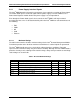
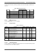
4.4.3 DC Specifications
All pins on the Intel
®
RMM are 3.3 volt tolerant with the exception of the USB signals, which are
USB compatible. The following sections describe the DC specifications of the signals.
au
3.3 V rail. The 3.3
iliary is operating in
and 3
e abs
W
th
V rai no than 1 m
Revision 1.0
28