
Technical Product Specification

IntelP®P Remote Management Module Environmental/Electrical Specifications Intel® Remote Management Module
4.4.1 Power Supply Interface Signals
r is present by the assertion of Power Good.
power supply. The Intel
®
RMM uses the
nd operational.
Even though the Power Good signal is de-asserted, the Intel
®
RMM is still fully functional.
Assuming the host server is s M can still communicate via
the following:
FM
IPMB
MII
US
Et
Ratings
ab m ratings for the Intel
®
Remote Management Module.
io um and minimum is neither implied nor guaranteed.
ratings may affect device reliability. Although the Intel RMM contains
protective circuitry to resist damage from static discharge, always take precautions to avoid high
The Intel
®
RMM determines that main system powe
The Power Good input is a buffered signal from the
Power Good signal to monitor whether the power supply is on a
till attached to AC power the Intel
®
RM
L
B
cetera
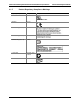
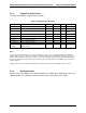
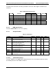
4.4.1.1 Maximum
The t le below contains absolute maximu
Funct nal operation at the absolute maxim
The Intel
®
RMM should not receive a clock while subjected to these conditions. Extended
exposure to the maximum
®
static voltages or electric fields.
Table 6. Absolute Maximum Ratings
Symbol Parameter Minimum Maximum Unit
Top Operating temperature under bias 0 70
°C
Tstorage Storage temperature -65 150
°C
Vcc Core and IO power supply voltage (3.3V +/- 10%) 3.0 3.6 V
Vcca Core and IO auxiliary power supply voltage (3.3V +/- 10%) 3.6 5.5
Vcc1.8 IO auxiliary power supply voltage (1.8V +/- 10%) -0.5 5.0 V
Vin3.3 Input voltage range for 3.3V IO -0.5 7.0 V
Vin1.8 Input voltage range for 1.8V IO -0.5 2.5 V
Revision 1.0
26